
Connector and equipment box

A technology of connectors and equipment, which is applied in the direction of connection, fixed connection, and parts of connection devices, etc., can solve the problems of low life of contacts and inconvenient maintenance, etc., and achieve high life, not easy to deform, and solve inconvenient maintenance. Effect

Pending Publication Date: 2021-03-12
CHINA AVIATION OPTICAL-ELECTRICAL TECH CO LTD
View PDF1 Cites 0 Cited by
  • Summary
  • Abstract
  • Description
  • Claims
  • Application Information

AI Technical Summary

Problems solved by technology

[0005] The purpose of the present invention is to provide a connector, which is used to solve the problems of the current connectors that deform the contacts to compensate for the position deviation of the connector during installation, resulting in a relatively low service life of the contacts and inconvenient maintenance; in addition, the present invention The object is also to provide an equipment box using the above connector

Method used


Image

  • Connector and equipment box
  • Connector and equipment box
  • Connector and equipment box

Examples


specific Embodiment 1

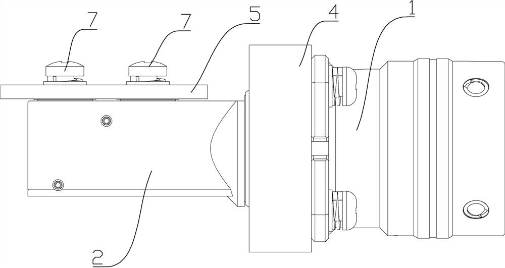
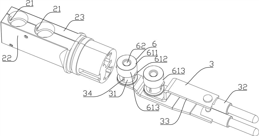
[0059] Such as Figures 1 to 10 As shown, the connector of the present invention is a transfer connector, and the front end of the connector is used to connect to the printed plate 5, and the backend is used to plug with the adapter plug.

[0060] The connector includes a housing 1, an insulator 2, and a contact 3, and the housing 1 is a metal conductive casing, which is fixed to the wall wall of the apparatus casing 4 by a bolt, and a connector mounting hole, a connector is opened. The contacts 3 and the insulator 2 are inserted into the apparatus casing 4 through the connector mounting hole, and is connected to the printed plate 5 in the equipment case 4, and the printed plate 5 includes a plate body 51 and a printed plate conductive portion 52. The equipment case 4 is electrically in contact with the housing 1 of the connector to achieve the shield of the contact 3 in the casing 1.

[0061] The insulator 2 is fixed to the housing 1, and the front end extends into the apparatus c...

specific Embodiment 2

[0081] Specifically Example 2 of the apparatus of the present invention, the structure of the apparatus in the present embodiment and the above embodiment is only, such as Figure 11 with Figure 12 As shown in the present embodiment, the printed plate conductive portion 52 includes a plate electrical conductive portion 521 fixed to the plate body 51 of the printed plate 5 and a adapter 522 that is electrically conductively electrically conductive with the plate body conductive portion 521. The adapter 522 is pressed against the contact cap 61 to conduct electrically contact.


PUM


Abstract

The invention relates to a connector and an equipment box. The connector comprises a shell, an insulator, a contact piece and a switching conductive piece. And the switching conductive piece is in up-down conductive sliding fit with the contact piece and is used for conducting electricity with a printed board conductive part on the printed board, so that the contact piece can be conductively connected with the printed board at different upper and lower positions through the switching conductive piece. When the position between the contact piece and the printed board is changed, the switching conductive piece can compensate the position deviation between the contact piece and the printed board, because the switching conductive piece is in sliding fit with the contact piece, the contact piece is not easy to deform, the switching conductive piece is not easy to deform, and the contact piece and the switching conductive piece can be normally used and installed for multiple times after being disassembled and assembled. The service life is long, and the problems that the service life of the contact element is short and the maintenance is inconvenient due to the fact that the contact element is deformed to supplement the position deviation of the connector when the existing connector is installed are solved.

Description

Technical field [0001] The present invention relates to a connector and a device box. Background technique [0002] Some devices are fixedly provided with printed boards to connect the printed boards in the equipment box and the equipment boxes, which generally install the external socket on the wall of the equipment cabinet, and then passed through the transfer plate The connector connects the external socket to the printed board for transmission of power or signals. [0003] Due to limited space in the equipment box, the existing installation order is to connect the printed board connector to the printed board, and then fix the printed board in the equipment box, and finally can insert the external connector into the equipment box. The body is inserted with the printed board connector, because the external connector is directly plugged directly from the printed board connector during the installation process, which cannot be changed, if the external connector is inserted into t...

Claims


Application Information

Patent Timeline
Patent Type & Authority Applications(China)
IPC IPC(8): H01R12/55H01R13/631H01R12/70
CPCH01R12/55H01R12/7047H01R13/6315
Inventor 王恒李立新柳先波刘向阳许蔚全硒硼张志中
Owner CHINA AVIATION OPTICAL-ELECTRICAL TECH CO LTD
Learn More