Power utilization comprehensive monitoring system

A comprehensive monitoring system and electricity consumption technology, applied in the direction of electrical components, circuit devices, electric fire alarms, etc., can solve the problem of outdated monitoring mode, fire accidents that cannot be quickly evacuated and eliminated, and firefighters who are not familiar with the site and other issues, to achieve the effect of easy viewing

Active Publication Date: 2021-03-12
HANGZHOU KAIDA ELECTRIC POWER CONSTR
View PDF4 Cites 3 Cited by
  • Summary
  • Abstract
  • Description
  • Claims
  • Application Information

AI Technical Summary

Problems solved by technology

[0004] The purpose of the present invention is: in order to solve the problem that the monitoring mode of commercial electricity consumption in the prior art is relatively backward, the total statistics of electricity consumption in a region are generally carried out. It is troublesome for power users to check the power consumption situation, and at the same time, the power consumption cannot be well displayed. In this way, if there is an abnormal situation, neither the staff nor the power users can effectively detect it. However, it is still inconvenient to deal with emergency situations, and if the computer room has a large site, it is impossible to quickly evacuate and eliminate the disaster when a serious fire accident occurs, and the firefighters are not familiar with the internal environment of the site. The fire extinguishing of firefighters brings some inconvenience, and a comprehensive monitoring system for electricity consumption is proposed

Method used


Image

  • Power utilization comprehensive monitoring system
  • Power utilization comprehensive monitoring system
  • Power utilization comprehensive monitoring system

Examples


Embodiment Construction

[0037] The following will clearly and completely describe the technical solutions in the embodiments of the present invention with reference to the accompanying drawings in the embodiments of the present invention. Obviously, the described embodiments are only some, not all, embodiments of the present invention. Based on the embodiments of the present invention, all other embodiments obtained by persons of ordinary skill in the art without creative efforts fall within the protection scope of the present invention.

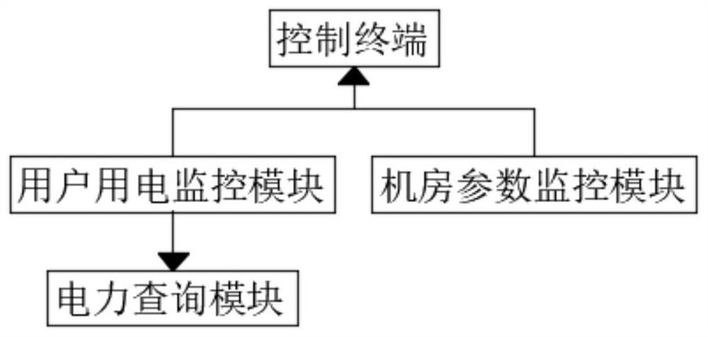
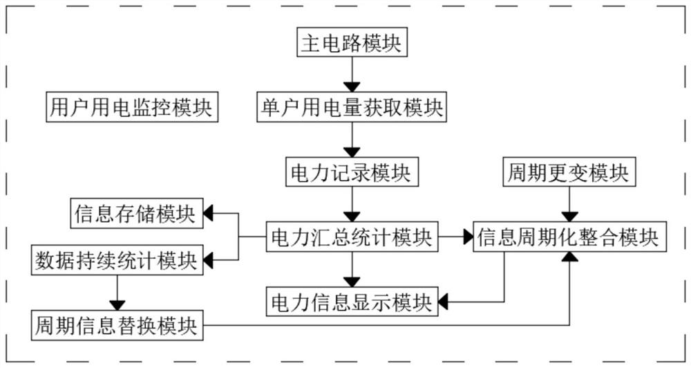
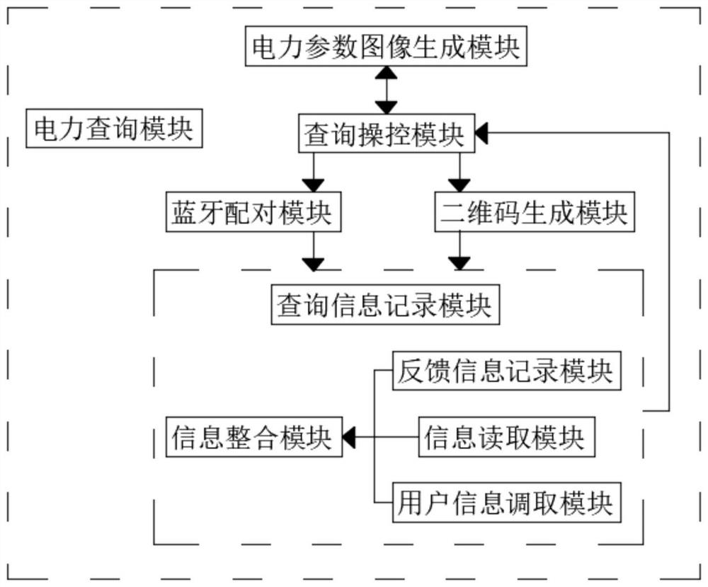
[0038] see Figure 1-7 , the present invention provides a technical solution: a comprehensive monitoring system for power consumption, including a control terminal, a user power consumption monitoring module, a machine room parameter monitoring module and a power query module, the input terminal of the control terminal and the user power consumption monitoring module The output end is electrically connected to the output end of the computer room parameter monitorin...


PUM


Abstract

The invention discloses a comprehensive power utilization monitoring system, and belongs to the technical field of commercial power monitoring. The system comprises a control terminal, a user power utilization monitoring module, a machine room parameter monitoring module and a power query module, and is characterized in that the input end of the control terminal is electrically connected with theoutput end of the user power utilization monitoring module and the output end of the machine room parameter monitoring module; and the input end of the power query module is electrically connected with the output end of the user power utilization monitoring module. According to the invention, the single-household power consumption acquisition module is arranged, and the fault detection module, theshort-circuit early warning module, the power consumption load monitoring module, the voltage monitoring module and the current rate monitoring module can detect the power consumption condition of asingle household, and can discover and process the condition in time; the electricity consumption recording module can record electricity consumption and electricity consumption conditions of a singlehousehold and transmit the electricity consumption and the electricity consumption conditions to the electric power summarizing and counting module, the electric power summarizing and counting moduletransmits information to the electric power information display module, and the electric power information display module displays daily electric power conditions.

Description

technical field [0001] The invention belongs to the technical field of commercial power monitoring, and in particular relates to a comprehensive monitoring system for power consumption. Background technique [0002] Electricity is an energy source powered by electrical energy. Invented in the 1870s, the invention and application of electricity set off the second industrialization climax. It has become one of the three scientific and technological revolutions in the world since the 18th century in human history. Since then, technology has changed people's lives. Even in today's Internet age, we still have a growing demand for electricity, because we have invented more products that use electricity, such as computers and home appliances. It is undeniable that the continuous emergence of new technologies has made electricity a necessity for people. [0003] In the existing technology, the monitoring mode of commercial electricity consumption is relatively backward. Generally...

Claims


Application Information

Patent Timeline
Patent Type & Authority Applications(China)
IPC IPC(8): H02J13/00A62C31/00A62C37/40G08B17/00G08B17/06G08B17/10G08B17/12
CPCH02J13/00001H02J13/00002A62C31/005A62C37/40G08B17/00G08B17/06G08B17/10G08B17/125
Inventor 胡春磊徐红艳李楠
Owner HANGZHOU KAIDA ELECTRIC POWER CONSTR
Why Eureka
Try Eureka