
Physical resource allocation method

An allocation method and technology of physical resources, applied in the field of physical resource allocation, can solve the problems of non-discovery, affecting system performance, and failure to obtain channel status in time, so as to avoid the waste of air interface resources.

Active Publication Date: 2021-03-12
杭州红岭通信息科技有限公司
View PDF8 Cites 0 Cited by
  • Summary
  • Abstract
  • Description
  • Claims
  • Application Information

AI Technical Summary

Problems solved by technology

When various physical resources conflict, there is a possibility of discarding or missing certain information, resulting in the inability to obtain measurement information or scheduling requests in time, which will greatly affect system performance and deteriorate user experience
At the same time, no reasonable and effective physical resource method for allocating SR, CSI, SRS and measuring gap has been found in the prior art
[0004] In the prior art, more SRS, SR and CSI feedback resources are allocated first, and for the SRS, SR, and CSI feedback resources, the number of users that can be allocated on each subframe is different. Release, resulting in continuous updating of resources, so that the allocated SRS, SR and CSI feedback resources have a certain randomness in the time domain, so that when allocating measurement slots, one or more of these three resources will fall In the measurement time slot, the base station side cannot obtain the required corresponding information as expected. If there is a lack of SRS, the uplink channel will not be measured in time; if there is no SR, the uplink data will not be scheduled in time; if there is no CSI feedback, the downlink The channel status is not obtained in time
In addition, in the existing technology, the reference signal used for mobility measurement in neighboring cells falls outside the measurement slot, while the NZP CSI RS used for CSI measurement in the current cell falls within the measurement slot, which will lead to poor user performance. The measurement of neighboring cells and this cell may even lead to the failure of measurement, which will affect user performance and user experience as well as the overall system performance

Method used


Image

  • Physical resource allocation method

Examples


Embodiment Construction

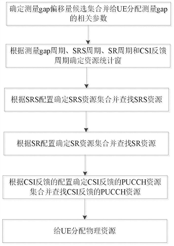
[0048] Embodiments of the present invention will be described in detail below in conjunction with the accompanying drawings. Such as figure 1 Shown, method of the present invention comprises the following steps:

[0049] Step 1. Determine the measurement gap offset candidate set and assign the relevant parameters of the measurement gap to the UE. The allocation measurement gap includes the corresponding measurement gap period, measurement gap duration (gapLen) and offset. The measurement gap period and measurement gap duration are based on the corresponding The gap pattern (pattern) is determined, combined with the measurement of the gap period, traversing the subframe indexes, and obtaining the candidate set of the measurement gap offset at the same time, the subframe is a subframe, which is a time unit in LTE and NR, and 1 subframe corresponds to 1 Milliseconds, one wireless frame corresponds to 10 subframes, numbered from 0 to 9:

[0050] Step 1.1, the measurement gap per...


PUM


Abstract

The invention discloses a physical resource allocation method. The method comprises the following steps: step 1, determining a gap offset measurement candidate set and allocating related parameters ofgap measurement to UE, step 2, determining a resource statistics window according to a gap measurement period, an SRS period, an SR period and a CSI feedback period, step 3, determining an SRS resource set according to SRS configuration and searching for SRS resources, and determining the SRS resource set according to the following steps: step 4, determining an SR resource set and searching for SR resources according to the SR configuration, and determining the SR resource set according to the following steps: step 5, determining a PUCCH resource set fed back by the CSI according to the configuration fed back by the CSI and searching for PUCCH resources fed back by the CSI; and step 6, allocating physical resources to the UE. The method has the advantages that the PUCCH resources fed backby the SRS, the SR and the CSI are determined in sequence according to the configuration of the measurement gap, so that the SRS, the SR and the CSI resources are staggered in time domain; and thus,smooth communication between the UE and the base station is ensured, and defects brought by the prior art are overcome.

Description

technical field [0001] The invention belongs to the technical field of communication, and in particular relates to a method for allocating physical resources. Background technique [0002] At present, in LTE (Long Term Evolution, long-term evolution) and NR (New Radio, new air interface), in the process of user equipment (User Equipment, UE) accessing the network, the base station will allocate various corresponding physical resources to the user equipment, For example, Sounding Reference Signal (SRS) for uplink channel measurement, PUCCH resources for downlink channel state (Channel State Information, CSI) feedback and uplink scheduling request (Schedule Request, SR), so that UE The downlink can also communicate with the base station normally and efficiently, thereby ensuring a good user experience. PUCCH (Physical Uplink Control Channel) is a physical uplink control channel; both CSI and SR are carried on PUCCH; such as LTE, SR and CSI are mapped on PUCCH format 1 and for...

Claims


Application Information

Patent Timeline
IPC IPC(8): H04L5/00H04W72/04
CPCH04L5/0048H04L5/0053H04L5/0057H04L5/0094H04W72/0446H04W72/21H04W72/23
Inventor 余秋星张文忠谭伟
Owner 杭州红岭通信息科技有限公司
Learn More