Shaping-controllable craniocerebral drainage tube

A drainage tube and cranial brain technology, applied in the field of cranial drainage tube, can solve problems such as not suitable for ventricular drainage application, inconvenient drainage tube indwelling and release process, lack of drainage tube, etc.

Pending Publication Date: 2021-03-16
昆明医科大学第二附属医院
View PDF0 Cites 0 Cited by
  • Summary
  • Abstract
  • Description
  • Claims
  • Application Information

AI Technical Summary

Problems solved by technology

[0003] The placement of the ventricular drainage tube, the indwelling and release of the drainage tube are the key points of ventricular drainage and nursing care. During the ventricular drainage, whether the drainage tube is unobstructed, whether the indwelling part of the drainage tube falls off, and whether the release is convenient or not all determine the success of the ventricular drainage; The drainage tube of the prior art adopts a silica gel drainage tube, because the volume of the drainage tube extending into the brain is small in itself, and the diameter of the drainage hole is small, causing intracranial hematoma to easily block the drainage hole, and the drainage is not smooth, and at the same time, the soft The drainage tube is almost zero in terms of drainage tube placement, indwelling support for the drainage channel, and avoidance of the risk of the drainage tube falling off. It is not suitable for the ventricular drainage process; Inability to easily release the drainage tube
[0004] To sum up, the existing technology lacks a special brain drainage tube with controllable shape. The existing drainage tubes are risky and inconvenient in the process of tube placement, drainage tube indwelling and release, and are not suitable for ventricular drainage.

Method used


Image

  • Shaping-controllable craniocerebral drainage tube
  • Shaping-controllable craniocerebral drainage tube
  • Shaping-controllable craniocerebral drainage tube

Examples


Embodiment 1

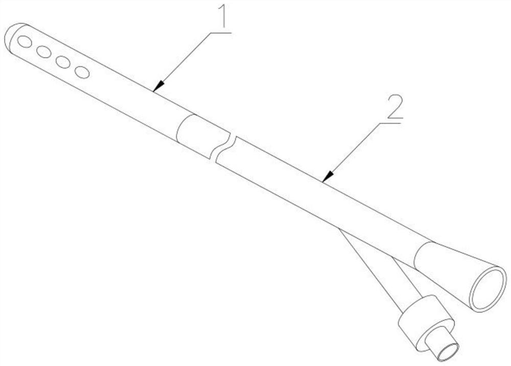
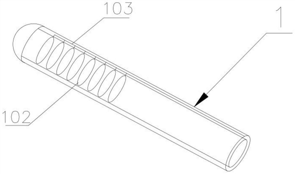
[0040] The controllable spring coil at the front end of the functional section of the present invention, under the action of the controllable spring coil, enables the head end of the functional section to have a guiding function, and at the same time has a fixing function after the drainage tube is placed to prevent the drainage tube from slipping;

[0041] The controllable spring coil of the functional section can achieve the effect of guiding and shaping under the action of the spring coil during the tube placement process of the drainage tube. Because the drainage tube itself of the functional section is made of flexible material, the built-in controllable spring The shape change of the ring can promote the shaping of the functional section. During the process of tube placement and indwelling, the shaped functional section can play a guiding role, and at the same time, it is not easy to slip off during indwelling.

Embodiment 2

[0043] The controllable spring coil at the front end of the functional section of the present invention, the controllable spring coil is located in the indwelling functional section to support the drainage tube to avoid the deformation of the drainage tube under pressure and affect the drainage, and the indwelling spring coil does not affect the drainage;

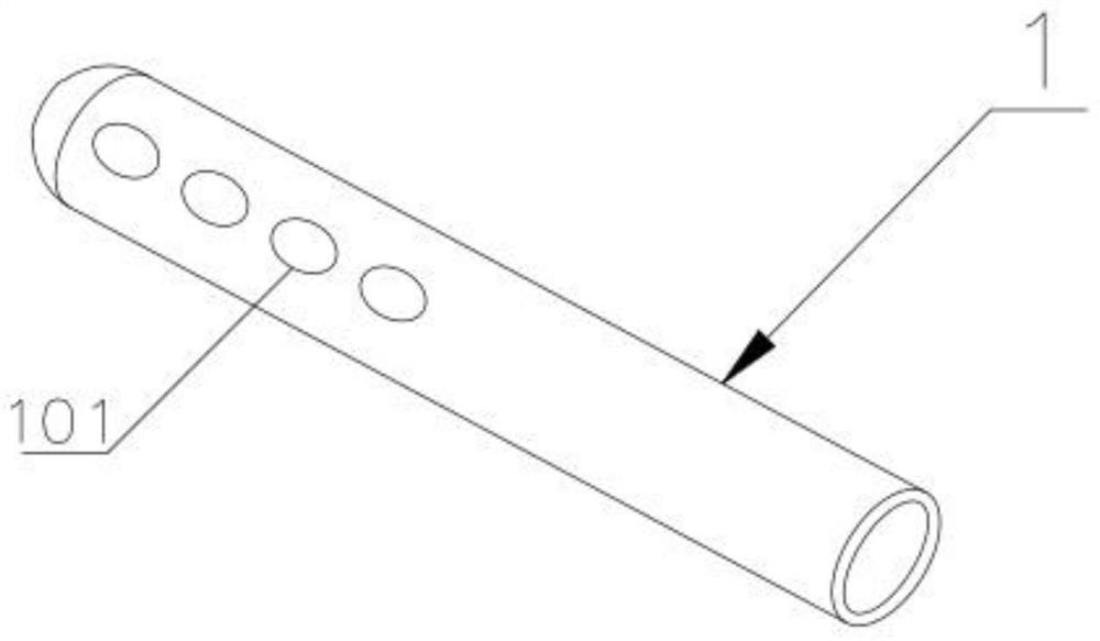
[0044] During the indwelling process of the functional section, the front end of the functional section is arc-shaped, and drainage holes are set at the front end and side ends for drainage. The conventional drainage tube has poor drainage effect due to the technical problems mentioned in the background technology, and Leading to serious consequences, the functional section of the present application uses a built-in spring coil to support the functional section during indwelling, and the drainage process will not cause blockage due to pressure and other reasons.

Embodiment 3

[0046] The controllable spring coil at the front end of the functional section of the present invention, the inner wall of the functional section is embedded with a stainless steel guide wire connected to the controllable spring coil, after electrolysis, the spring coil is electrolytically separated from the stainless steel guide wire of the functional section, and can be used along with the functional section lead out, so that the functional section becomes flexible and easy to take out the drainage tube;

[0047] The controllable spring coil on the inner wall of the functional section is an electrolytic spring coil, and the controllable spring coil also includes release auxiliary equipment; the controllable spring coil is fixed on the inner wall of the functional section in a point contact manner, and the controllable spring coil The ring can be fixed by single point contact or multi-point contact;

[0048] The inner wall of the functional section is embedded with a wire sta...


PUM


Abstract

The invention discloses a shaping-controllable craniocerebral drainage tube, and relates to the technical field of craniocerebral drainage tubes. The shaping-controllable craniocerebral drainage tubecomprises a drainage tube body, wherein the drainage tube body comprises a functional section and a drainage section which are integrally formed, the front end of the functional section is in an arc shape, drainage holes are formed in the front end and the side end of the functional section, a controllable spring ring is arranged on the inner wall from the front end to the tail end of the functional section, and the controllable spring ring controls shaping, supporting and disengagement of the functional section to take out the drainage tube. According to the shaping-controllable craniocerebral drainage tube, the indwelling end of the drainage tube can be shaped in a controllable mode, ventricular drainage tube indwelling, indwelling and disengagement are facilitated, and the operation difficulty of the ventricular drainage tube indwelling and disengagement and the risk of drainage indwelling are reduced.

Description

technical field [0001] The invention relates to the technical field of brain drainage tubes, in particular to a shape-controllable brain drainage tube. Background technique [0002] Ventricular drainage is one of the commonly used treatment measures after craniocerebral surgery. It can not only quickly reduce intracranial pressure, discharge intracerebral hemorrhage, but also reduce wound cerebrospinal fluid leakage, relieve meningeal irritation symptoms, prevent meningeal adhesions, and occlusion of arachnoid granules , Reduce cerebral edema, avoid suboccipital intermuscular fluid at the same time, and help improve surgical field exposure during surgery. [0003] The placement of the ventricular drainage tube, the indwelling and release of the drainage tube are the key points of ventricular drainage and nursing care. During the ventricular drainage, whether the drainage tube is unobstructed, whether the indwelling part of the drainage tube falls off, and whether the release...

Claims


Application Information

Patent Timeline
Patent Type & Authority Applications(China)
IPC IPC(8): A61M25/14
CPCA61M25/0052A61M25/0068A61M25/007A61M2025/0063A61M2210/0687A61M2210/005
Inventor 黄晓斌蒲军赵金喜刘旭杰周玮林田锦涛陈希许智星赵钰姚华逸
Owner 昆明医科大学第二附属医院
Why Eureka
Try Eureka