A storage rack surface cleaning and dust removal equipment for logistics
A technology for surface cleaning and dust removal equipment, which is applied in the direction of using tools, cleaning methods and utensils, chemical instruments and methods, etc. Equipment work efficiency and the effect of improving cleaning efficiency
- Summary
- Abstract
- Description
- Claims
- Application Information
AI Technical Summary
Problems solved by technology
Method used
Image
Examples
Embodiment 1
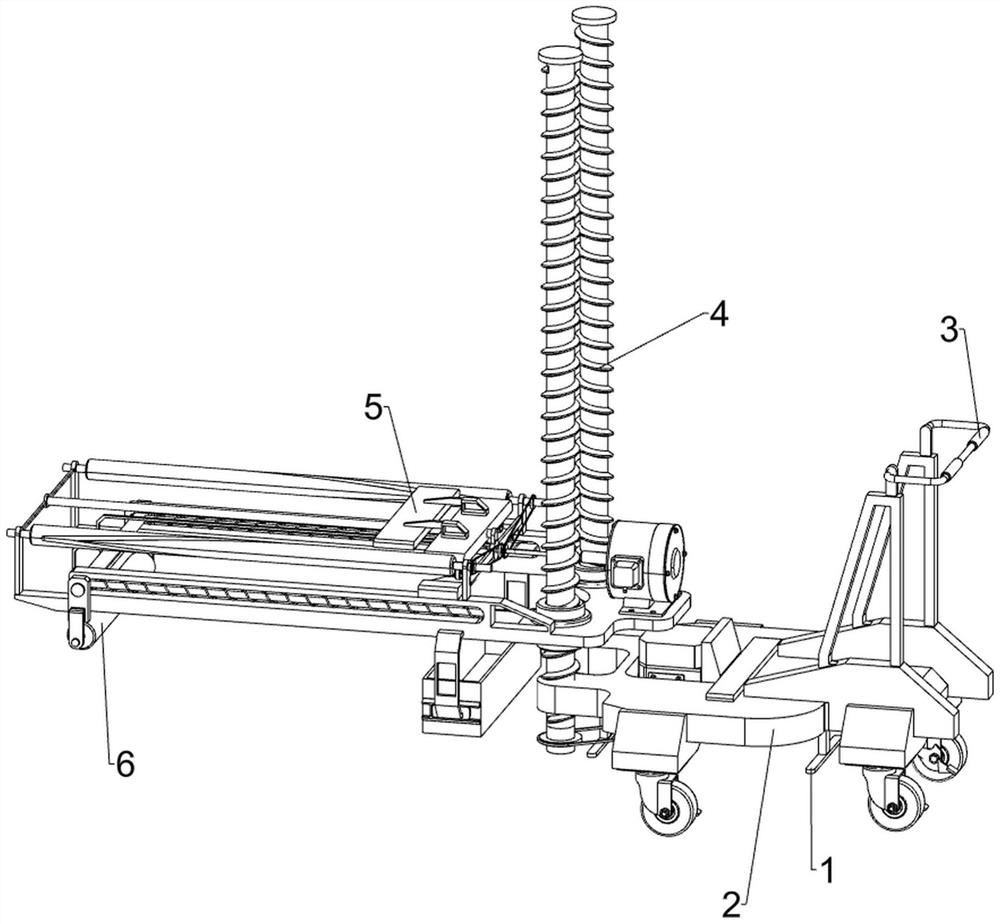
[0027] Such as figure 1 As shown, a storage rack surface cleaning and dust removal equipment for logistics, including a base 1, a support plate 2, a handle 3, a lifting mechanism 4, a spraying mechanism 5 and a cleaning mechanism 6, the top of the base 1 is provided with a support plate 2, a support plate 2 One side of the top is provided with a handle 3, the top of the support plate 2 is provided with a lifting mechanism 4 on the side away from the handle 3, the upper side of the lifting mechanism 4 is provided with a spraying mechanism 5, and the lower part of the lifting mechanism 4 is provided with a cleaning mechanism 6 on the side away from the spraying mechanism 5 .
[0028] To clean and dust the surface of the logistics storage rack, the lifting mechanism 4 first adjusts the cleaning tools to the corresponding layer of the storage rack, then the spraying mechanism 5 moves and sprays the cleaning agent, and then the cleaning mechanism 6 performs rolling cleaning. It ca...
Embodiment 2
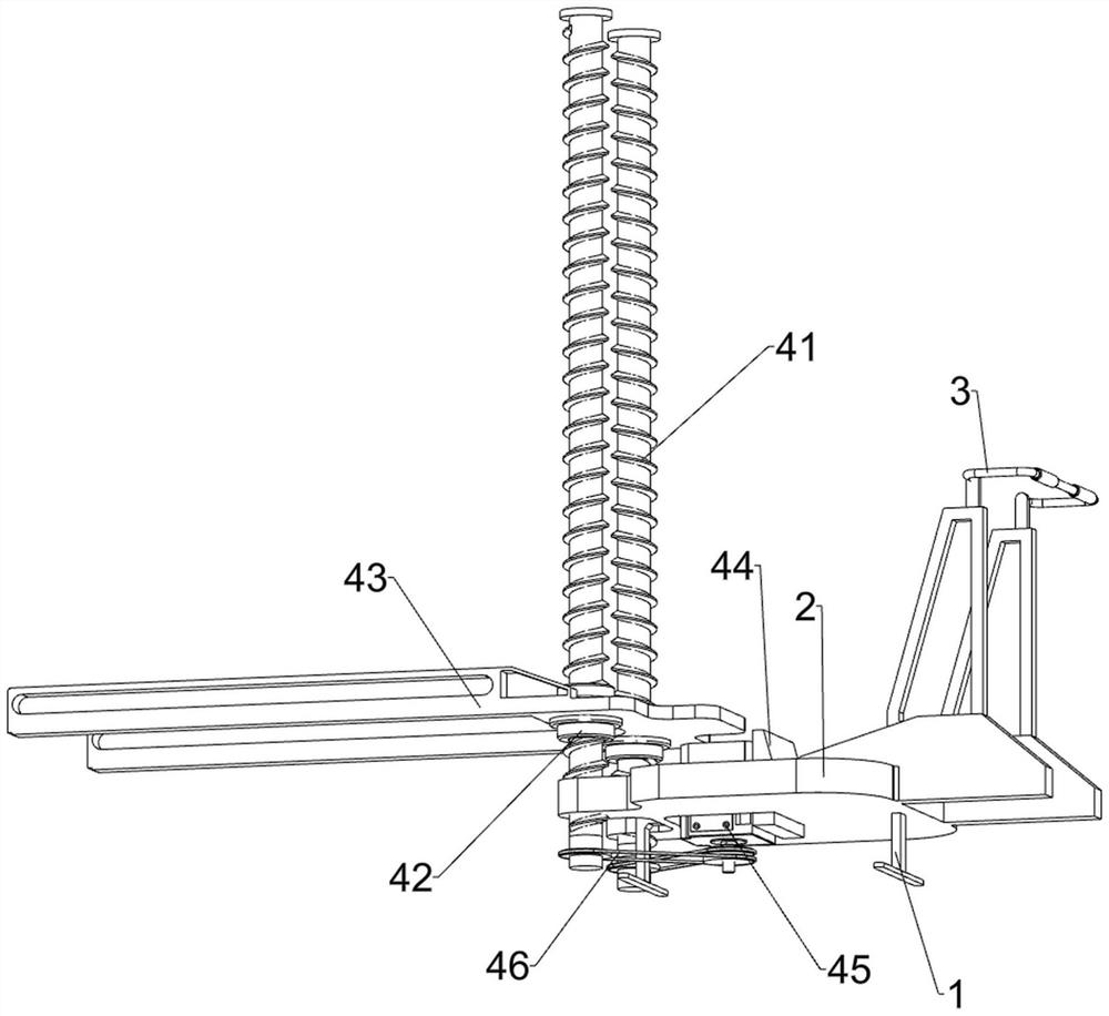
[0030] Such as figure 2 , image 3 with Figure 4 As shown, on the basis of Embodiment 1, the lifting mechanism 4 includes a screw rod 41, a nut 42, a lifting plate 43, a first fixed block 44 and a first servo motor 45, and the top of the support plate 2 passes through the side away from the handle 3. Bearing symmetrical rotation is provided with two screw mandrels 41, on the screw mandrel 41, a nut 42 is slidably arranged, a lifting plate 43 is arranged between the outer surfaces of the nuts 42, and a first fixed block 44 is arranged in the middle of the top of the support plate 2. One side of the fixed block 44 is provided with a first servo motor 45 , and the output shaft of the servo motor is connected to the screw rod 41 through a first pulley assembly 46 .
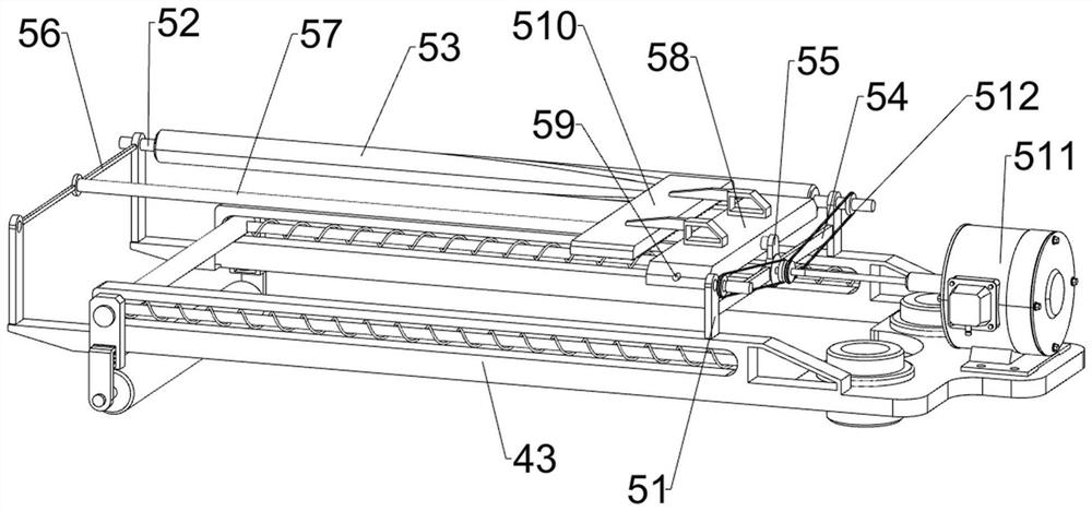
[0031] The spraying mechanism 5 includes a first bearing seat 51, a first rotating shaft 52, a V-shaped groove cylinder 53, a second bearing seat 54, a second fixed block 55, a third fixed block 56, a first guide ...
Embodiment 3
[0035] Such as Figure 5 with Image 6 As shown, on the basis of Embodiment 2, it also includes a fourth bearing seat 7, a second rotating shaft 8, a swing rod 9, a third elastic member 10, a wedge block 11, a limit block 12, a fixed rod 13, a first Five bearing housings 14 and rotating rods 15, both sides of the bottom of the first slider 58 are provided with fourth bearing housings 7, the fourth bearing housing 7 is provided with a second rotating shaft 8 in a rotating manner, and one end of the second rotating shaft 8 is provided with a swing rod 9. A third elastic member 10 is sleeved in the middle of the second rotating shaft 8. Wedge blocks 11 are arranged on both sides of the top of the lifting plate 43. Limiting blocks 12 are arranged on the slope of the wedge block 11. A fixed rod 13 is symmetrically arranged in the middle of the lifting plate 43. , the end of the fixed rod 13 close to the screw rod 41 is provided with a fifth bearing seat 14, and the fifth bearing s...
PUM
 Abstract
Description
Claims
Application Information
 - R&D
- Intellectual Property
- Life Sciences
- Materials
- Tech Scout
- Unparalleled Data Quality
- Higher Quality Content
- 60% Fewer Hallucinations
Browse by: Latest US Patents, China's latest patents, Technical Efficacy Thesaurus, Application Domain, Technology Topic, Popular Technical Reports.
© 2025 PatSnap. All rights reserved.Legal|Privacy policy|Modern Slavery Act Transparency Statement|Sitemap|About US| Contact US: help@patsnap.com


