Push type steel ball polishing device

A push type, steel ball technology, applied in the direction of grinding/polishing safety device, grinding feed movement, grinding workpiece support, etc., can solve problems such as difficult to handle particles, and achieve the effect of high safety performance

Pending Publication Date: 2021-03-16
阳龄苇
View PDF6 Cites 1 Cited by
  • Summary
  • Abstract
  • Description
  • Claims
  • Application Information

AI Technical Summary

Problems solved by technology

[0005] In order to overcome the shortcomings in the prior art that require people to manually load and unload particles that are difficult to handle, the technical problem is to provide a push-type steel ball grinding device that can automatically load and unload and can absorb the generated particles

Method used


Image

  • Push type steel ball polishing device
  • Push type steel ball polishing device
  • Push type steel ball polishing device

Examples


Embodiment 1

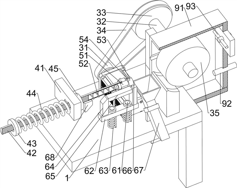
[0027] A push-type steel ball grinding device, such as figure 1 , figure 2 , Figure 4 and Figure 5 As shown, it includes a worktable 1, a motor 2, a grinding mechanism 3, a limit mechanism 4 and a stabilizing mechanism 5, a motor 2 is installed in the middle of the top rear side of the workbench 1, and a grinding mechanism 3 is arranged between the motor 2 and the workbench 1 , The top left side of the workbench 1 is provided with a limit mechanism 4, and the right side of the limit mechanism 4 is provided with a stabilizing mechanism 5.

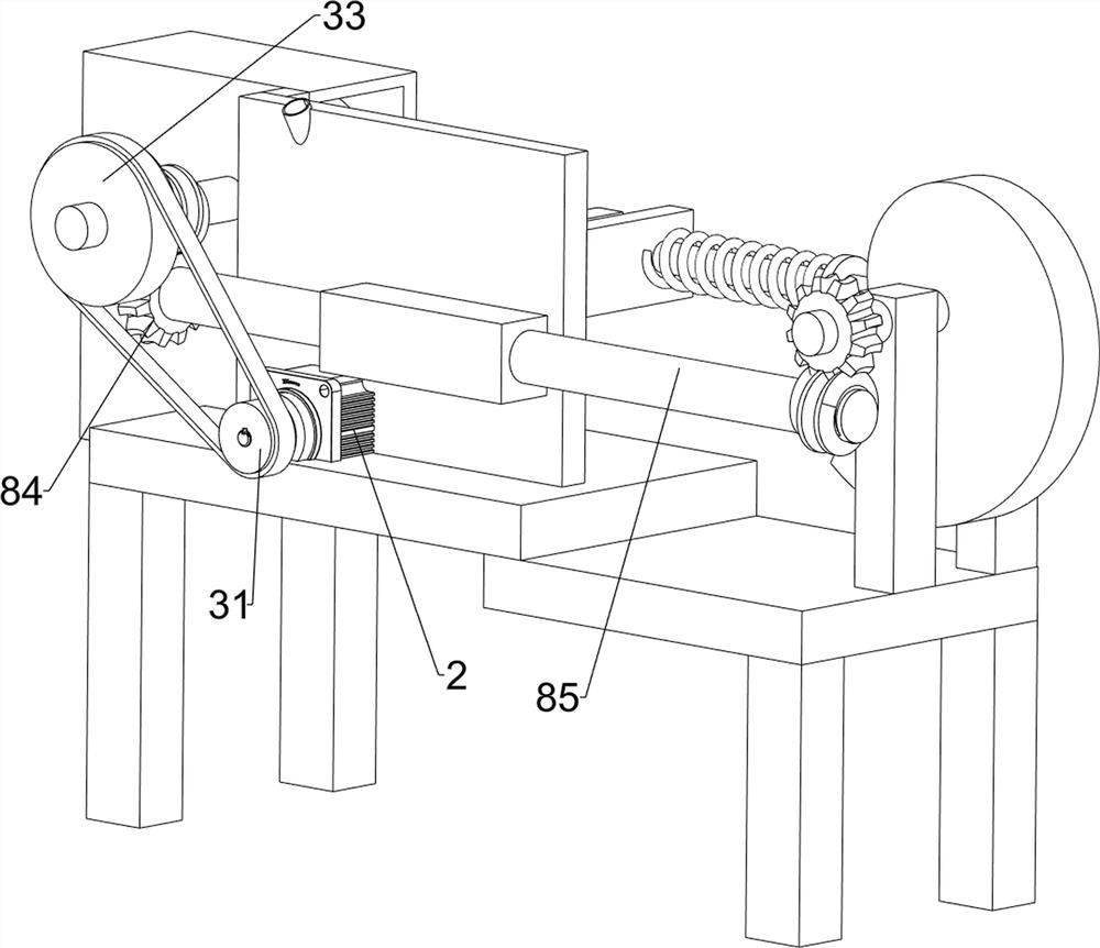
[0028] The grinding mechanism 3 includes a first transmission wheel 31, a first rotating shaft 32, a second transmission wheel 33, a belt 34 and a polishing wheel 35. The rear part of the output shaft of the motor 2 is connected with the first transmission wheel 31, and the top right rear of the workbench 1 The side rotation type is provided with a first rotating shaft 32, the rear of the first rotating shaft 32 is connected with a sec...

Embodiment 2

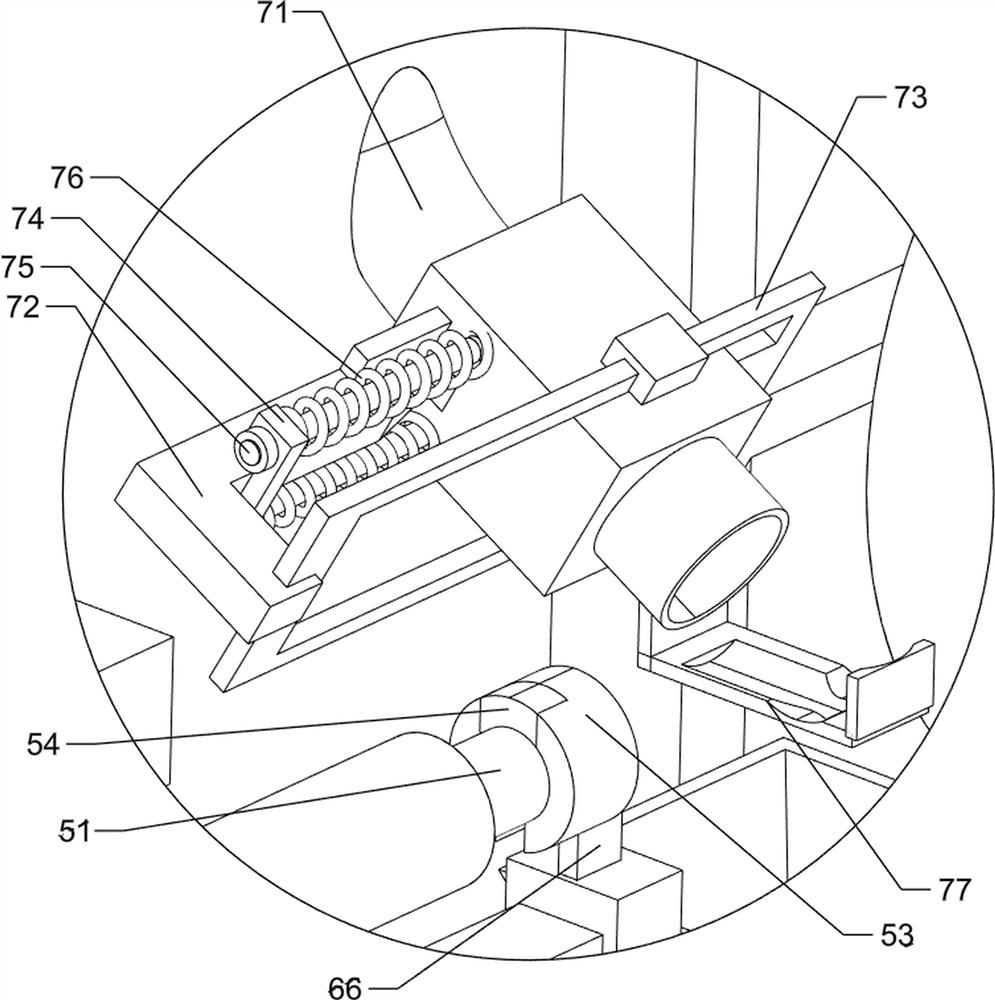
[0033] On the basis of Example 1, such as figure 2 , image 3 , Figure 4 and Figure 5 As shown, it also includes a blanking mechanism 6, and the blanking mechanism 6 includes a first guide rod 61, a first connecting block 62, a third spring 63, a first wedge block 64, a first stop block 65, a clamping block 66, The collection groove 67 and the second wedge block 68, the first guide rod 61 is symmetrically connected in the middle of the front side of the top of the workbench 1, and the first guide rod 61 is slidably provided with the first connecting block 62, and the first connecting block 62 and There are third springs 63 symmetrically connected between the worktables 1. The third springs 63 are respectively set on the first guide rods 61. The first wedge-shaped block 64 is connected to the left side of the top of the first connecting block 62. The top of the first connecting block 62 The right side is connected with a block 66, and the block 66 cooperates with the chut...


PUM


Abstract

The invention relates to a grinding and polishing device, in particular to a push type steel ball polishing device. The technical problem is to provide a push type steel ball polishing device which can automatically feed and discharge and can absorb generated particles. The push type steel ball polishing device comprises: a workbench, wherein a motor is installed in the middle of one side of the workbench; a polishing mechanism arranged between the motor and the workbench; a limiting mechanism arranged on one side of the workbench; and a stabilizing mechanism arranged on the limiting mechanism. The device achieves the effects that automatic feeding and discharging can be achieved, and the generated particles can be absorbed; people only need to place steel balls in a material guide pipe; and the steel balls can be intermittently pushed to a material receiving plate when a first push rod moves leftwards and rightwards and attracted through a magnet.

Description

technical field [0001] The invention relates to a grinding device, in particular to a pushing type steel ball grinding device. Background technique [0002] Steel ball is a kind of sphere with smooth surface, which can be used as the basic component in the bearing, widely used in various industries, and a good steel ball needs to be polished, and can only be put into use when it reaches a certain standard. [0003] Existing grinding device, as the Chinese patent that patent announcement number is CN211103170U discloses a kind of steel ball grinding device, described steel ball grinding device comprises base plate; On the top, the four support columns are distributed in a rectangular array; on the top plate, the top plate is fixedly installed on top of the four support columns. There are certain deficiencies in the above-mentioned patents, which require people to manually load and unload materials, which will greatly reduce work efficiency, and certain particles will be prod...

Claims


Application Information

Patent Timeline
Patent Type & Authority Applications(China)
IPC IPC(8): B24B29/04B24B41/00B24B41/06B24B55/06B08B3/02
CPCB24B29/04B24B41/005B24B41/00B24B41/06B24B55/06B08B3/02
Inventor 阳龄苇
Owner 阳龄苇
Why Eureka
Try Eureka