Gluing machine applied to production and processing of hollow glass

A technology of glue machine and glass, applied in the field of glue machine, can solve the problems of increasing the cleaning work of on-site operators, collecting glue liquid, unfavorable for the production and processing of insulating glass, etc.

Inactive Publication Date: 2022-01-14
江苏诚成节能玻璃有限公司
View PDF1 Cites 1 Cited by
  • Summary
  • Abstract
  • Description
  • Claims
  • Application Information

AI Technical Summary

Problems solved by technology

[0004] However, the technical solution provided by this patent cannot collect the overflowing glue during the glue making process of the glue machine, causing the overflowed glue to flow directly on the equipment or the ground, which not only causes the glue At the same time, the overflowing rubber material also pollutes the working environment, which increases the cleaning work of the on-site operators, which is not conducive to the production and processing of insulating glass

Method used


Image

  • Gluing machine applied to production and processing of hollow glass
  • Gluing machine applied to production and processing of hollow glass
  • Gluing machine applied to production and processing of hollow glass

Examples


Embodiment 1

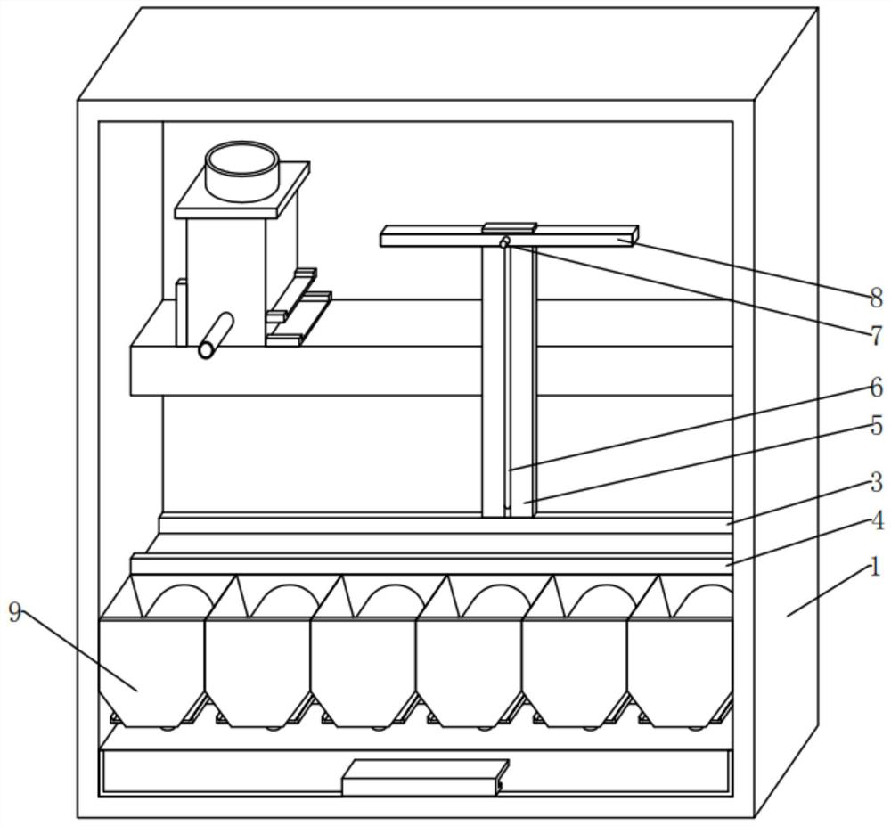
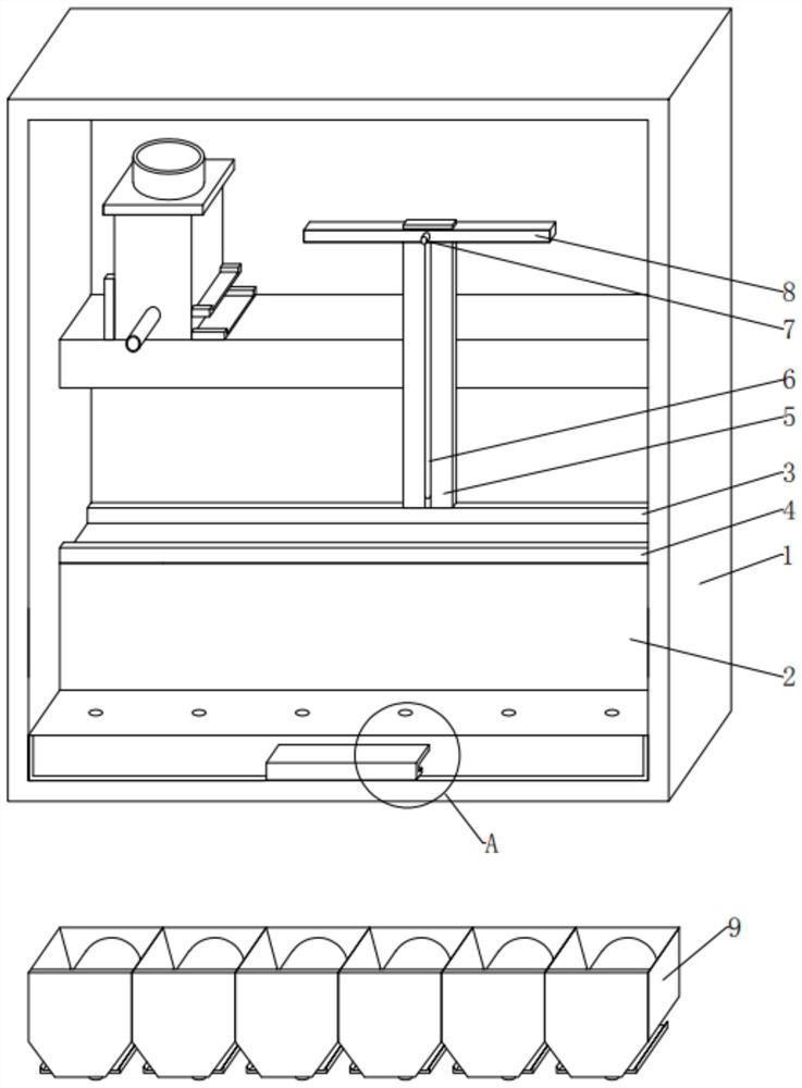
[0048] see Figure 1-3 , in an embodiment of the present invention, a gluing machine applied to the production and processing of insulating glass, including:

[0049] The main body of the glue machine 1 is fixedly installed with an operation table 2 at the bottom rear part between the left and right inner walls of the glue machine body 1, and the front and rear ends of the top outer surface of the operation table 2 are respectively fixedly installed with a fixed plate 3 and a movable Plate 4, the top position of moving plate 4 is left and right horizontal direction slides and is installed with fixed bar 5, and the front side middle end position of fixed bar 5 is provided with vertical chute 6 vertically up and down, and the top position of vertical chute 6 is fixed. A slide bar 8 is installed, and a fixed handle 7 is fixedly installed in the center of the front outer surface of the slide bar 8;

[0050] Glue-collecting assembly 9, the outer surface of the front side of the op...

Embodiment 2

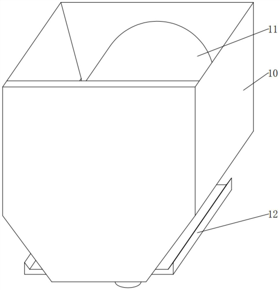
[0060] see Figure 4 , Figure 6-7 Compared with Embodiment 1, the embodiment of the present invention differs in that: the glue guide assembly 11 includes:

[0061] The convex plate 13 is fixedly installed in the middle of the upper end between the front and rear inner walls of the glue drop trough 10. The material of the convex plate 13 is boron-iron alloy. The letter "C" shape of °, there is an interval between the bottom of the left and right outer walls of the convex plate 13 and the left and right inner walls of the glue drop groove 10;

[0062] Here, the convex plate 13 and its appearance are set as upwardly convex on a longitudinal section and rotated 90° clockwise in the shape of the letter "C", which is to facilitate the arched shape to drop the top convex plate 13 of the glue drop chute 10. The glue can slide down to the left and right along the outer wall of the convex plate 13, and finally lead to the right guide plate 15 and the left guide plate 16, so that the...

Embodiment 3

[0074] see Figure 4-8 Compared with Embodiment 1, the embodiment of the present invention differs in that the flow aid assembly 12 includes:

[0075] The long groove, the left end and the right end of the glue drop groove 10 are obliquely opened with a hollow long groove from the middle end to the bottom position;

[0076] The long groove here is to separate the small cavity and the large cavity together with the longitudinal plate 17 to store quicklime powder and water respectively, and when the vertical plate 17 falls, the quicklime powder in the small cavity is moved along the direction of the long groove. The bottom slides into the large cavity and heats up after contacting with water;

[0077] The short groove, the middle upper end of the long groove is vertically provided with a hollow short groove, and the bottom of the short groove extends downward to the upper end of the left and right ends of the glue drop groove 10 and is provided with an outlet;

[0078] The sho...


PUM


Abstract

The invention provides a gluing machine applied to production and processing of hollow glass. The gluing machine comprises: a gluing machine body, wherein an operation table is fixedly mounted at the rear position of the bottom end between the left inner wall and the right inner wall of the gluing machine body; and glue collecting assemblies, wherein the glue collecting assemblies capable of conveniently collecting overflowing glue liquid are fixedly installed on the outer surface of the front side of the operation table in the left-right horizontal direction in an adjacent column mode, and each glue collecting assembly comprises a glue falling groove, a glue guiding assembly capable of guiding the overflowing glue liquid to be collected and a flow assisting assembly capable of conveniently collecting the glue liquid in a downward flowing mode and preventing accumulation. According to the gluing machine applied to hollow glass production and processing, in the gluing process of the gluing machine, overflowing glue liquid can be collected, the overflowing glue liquid is prevented from directly flowing on equipment or the ground, and loss and waste of the glue liquid are avoided; and a clean working environment is ensured, the cleaning work of field operators is reduced, and the production and processing effects of hollow glass are facilitated.

Description

technical field [0001] The invention relates to the technical field of gluing machines, more specifically, to a gluing machine used in the production and processing of insulating glass. Background technique [0002] At present, there is no device for fixing the insulating glass in the gluing machine used for processing insulating glass, so that the insulating glass is not fixed when gluing; and for the insulating glass after gluing, the curing speed is low, which may affect production efficiency; [0003] In view of the above problems, regarding the technical problems such as the unfixed gluing of insulating glass and the low curing speed after gluing, after a large number of searches, a fully automatic insulating glass gluing machine with a patent number of CN202022310603.5 was found. Including the main body of the gluing machine, the inner end of the main body of the gluing machine is provided with an operation table, the upper end of the operation table is provided with a...

Claims


Application Information

Patent Timeline
Patent Type & Authority Applications(China)
IPC IPC(8): C03C27/10
CPCC03C27/10
Inventor 崔银标
Owner 江苏诚成节能玻璃有限公司
Why Eureka
Try Eureka