
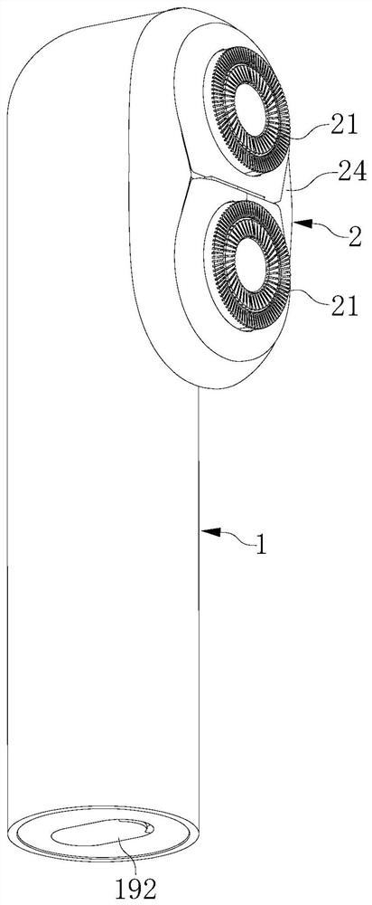
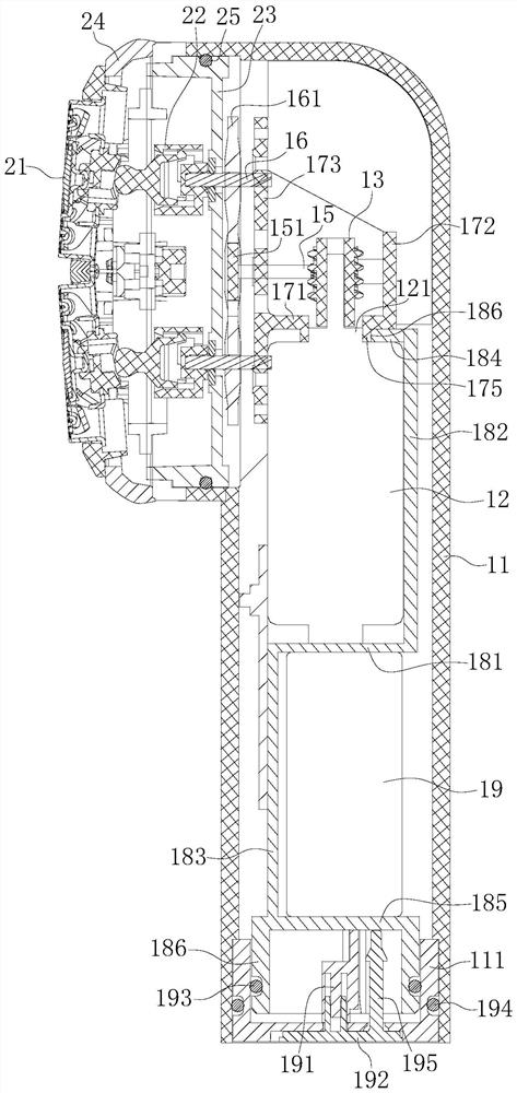
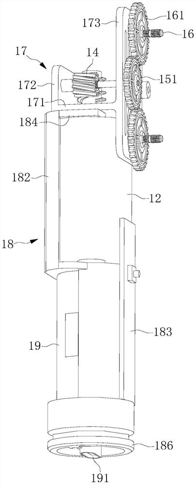
Transmission device and shaver

A transmission device and shaver technology, applied in the field of shaver, can solve the problems that the relative position cannot be guaranteed accurately, it is easy to cause impact and noise, and it is not easy to fit in place, etc. It achieves a compact structure, high installation accuracy, and low noise. Effect

Pending Publication Date: 2021-03-16
WUHU BEICI ELECTRICAL APPLIANCE CO LTD
View PDF1 Cites 3 Cited by
  • Summary
  • Abstract
  • Description
  • Claims
  • Application Information

AI Technical Summary

Problems solved by technology

The patent with the publication number CN211640004U discloses an electric shaver, the housing is provided with a motor, and the rotation of the motor is transmitted to the two shaft gears through the cooperation of the first bevel gear and the second bevel gear, thereby driving the two blades The group rotates and changes the direction of the two knife groups. However, with this structure, the two bevel gears are not easy to fit in place, and the fit is loose, which is easy to cause impact and noise. The transmission stability is poor, and the transmission ratio is small, and one end of the transmission shaft It is set on the shell, and one end is set on the frame card. It is difficult to ensure the relative position of the shaft and the perpendicularity of the shaft when set on the two parts; the motor is set on the bracket, and the bevel gear on the top of the motor shaft is connected to the transmission shaft. Gear meshing, the two parts are set on different parts, the relative position cannot be guaranteed accurately, it is easy to cause impact and noise, and the transmission stability will be relatively poor; other key parts are set on different parts and cannot be modularized , the assembly is cumbersome, the assembly accuracy is low, and the product is complex and costly

Method used


Image

  • Transmission device and shaver
  • Transmission device and shaver
  • Transmission device and shaver

Examples


Embodiment Construction

[0036] The present invention will be described in detail below with reference to the accompanying drawings and examples.

[0037] It should be noted that the described embodiments are only some of the embodiments of the present invention, but not all of the embodiments. In the case of no conflict, the embodiments in the present application and the features in the embodiments can be combined with each other. Based on the embodiments of the present invention, all other embodiments obtained by persons of ordinary skill in the art without creative efforts fall within the protection scope of the present invention.

[0038] If there are directional indications (such as up, down, left, right, front, back...) in the embodiment of the present invention, the directional indications are only used to If the relative positional relationship, movement conditions, etc. between the components shown in the figure below are changed, if the specific posture changes, the directional indication w...


PUM


Abstract

The invention provides a transmission device and a shaver. The transmission device comprises a motor, a worm, a bevel gear, a driving shaft, at least one driven shaft and a transmission frame, whereinthe driving shaft and the at least one driven shaft are installed on the transmission frame in a rotating mode, the bevel gear is fixed to the driving shaft, the worm is fixed to an output shaft of the motor, the bevel gear is meshed with the worm, and the driving shaft is in transmission connection with the at least one driven shaft. According to the transmission device, transmission is achievedthrough matching of the worm and the bevel gear, compared with an existing bevel gear matching scheme, the worm and the bevel gear are matched in place more easily, installation precision is higher,meshing is tighter, and therefore transmission is more stable, transmission efficiency is higher, noise is low, the service life is longer, and the whole product is compact in structure, small in overall appearance size, and low in cost.

Description

technical field [0001] The invention relates to the technical field of shaver, in particular to a transmission device and a shaver. Background technique [0002] Electric shavers currently on the market generally include a body and a head cover assembly for shaving, and the head cover assembly is driven to rotate by a motor provided in the shaver body. The patent with the publication number CN211640004U discloses an electric shaver, the housing is provided with a motor, and the rotation of the motor is transmitted to the two shaft gears through the cooperation of the first bevel gear and the second bevel gear, thereby driving the two blades The group rotates and changes the direction of the two knife groups. However, with this structure, the two bevel gears are not easy to fit in place, and the fit is loose, which is easy to cause impact and noise. The transmission stability is poor, and the transmission ratio is small, and one end of the transmission shaft It is set on the...

Claims


Application Information

Patent Timeline
Patent Type & Authority Applications(China)
IPC IPC(8): B26B19/14B26B19/32B26B19/38
CPCB26B19/14B26B19/32B26B19/3853B26B19/3873
Inventor 汪专兴
Owner WUHU BEICI ELECTRICAL APPLIANCE CO LTD
Learn More