Pressure stabilizing mechanism

A pressure stabilization and voltage stabilization technology, which is applied in the field of pressure stabilization mechanisms, can solve the problems of low recycling rate of waste plastic polymer materials, waste of production costs, pollution of waste materials recycling, etc.

Inactive Publication Date: 2021-03-16
ZHEJIANG IND POLYTECHNIC COLLEGE
View PDF5 Cites 0 Cited by
  • Summary
  • Abstract
  • Description
  • Claims
  • Application Information

AI Technical Summary

Problems solved by technology

[0003] In the production process of the extruder, the raw material is heated in a limited and closed environment, and then extruded and transported by the screw, the material is extruded into the mold to form a stable raw material loose channel, while in the process of the extruder Among them, the pressure of the internal screw on the material also affects the normal production. In the normal use process, the internal pressure is often unstable and the production is unstable or defective.
[0004] In the production process of polymer plastics, a lot of waste is often generated, especially in the process of adjusting and styling large samples. A large amount of waste of raw materials will be generated. Usually, most production units will waste the waste. Recycling, using it for specific products or styles, because waste materials are mixed with more impurities and substances of different components, further pollution will also occur during the recycling of waste materials, and particles may also exist There are a large number of voids and gaps, and more air is mixed in them. During processing, different types of materials will produce different expansion pressures under the same heat, resulting in unstable pressure inside the extruder. The normal operation of the extruder, and the current material extrusion equipment cannot adapt to such a production situation, which also leads to a low recycling rate of plastic polymer material waste, resulting in a waste of production costs

Method used


Image

  • Pressure stabilizing mechanism
  • Pressure stabilizing mechanism
  • Pressure stabilizing mechanism

Examples


Embodiment 1

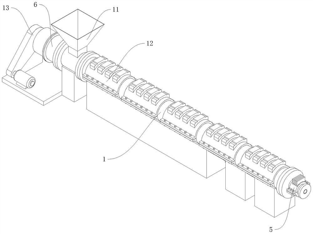
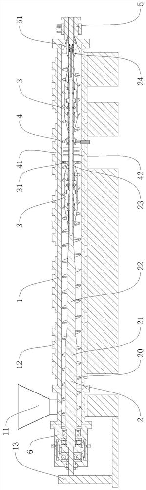
[0032] This embodiment discloses an extruder, referring to figure 1 and figure 2As shown, it includes a cylinder body 1 and a screw rod 2. The cylinder body 1 is divided into a feed end and a discharge end. A feed hopper 11 is installed on the feed end for raw materials to enter. , for the material to flow out; a heating device 12 is arranged on the outer periphery of the cylinder 1 to heat the material sheet in the cylinder 1; the screw 2 is connected to the inside of the cylinder 1 through the support device 6, and the outer periphery of the screw 2 is fixed with The screw blade 20 is driven to rotate by the driving mechanism 13 , and the screw blade 20 extrudes the heated and melted raw material from the discharge head 5 during the rotation. A plurality of pressure detection sensors are installed at various positions in the cylinder body 1 to monitor the material pressure parts in the cylinder body 1 .

[0033] In the extruder, the screw 2 includes a first rod segment 21...

Embodiment 2

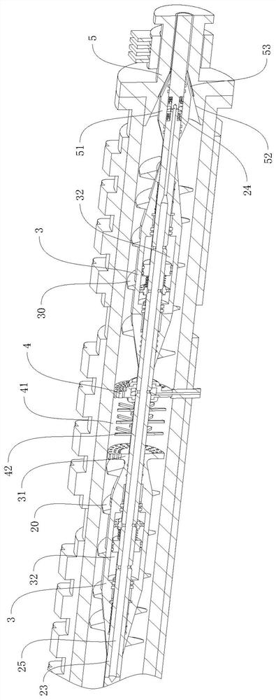
[0035] This embodiment discloses a pressure stabilization mechanism, refer to image 3 , 4 , 5, the mechanism can be installed in the plastic extruder as in the first embodiment, and mainly includes two voltage stabilizing sliding sleeves 3, and the two voltage stabilizing sliding sleeves 3 are sleeved on the outside of the screw rod 2, and can be opposite to the screw rod 2 are axially movable, and the internal structures of the two pressure stabilizing sliding sleeves 3 are similar, and are relatively upside down.

[0036] The outer wall of the voltage stabilizing sliding sleeve 3 is cylindrical in the middle, and the two ends are gradually tapered. The inner wall of the voltage stabilizing sliding sleeve 3 is adapted to the third rod end. A main pressure stabilizing chamber 32 is formed between the ring groove and the screw rod 2; the ring groove 33 is sealed at both ends of the pressure stabilizing main chamber 32, and a seal 2 331 is installed between the sealing ring gr...

Embodiment 3

[0044] This embodiment discloses a pressure stabilizing mechanism. On the basis of the second embodiment, in order to further increase the effect of the pressure fit, the axial movement of the pressure stabilizing sliding sleeve 3 is further guided and restricted. On the inner wall of the voltage stabilizing sliding sleeve 3, a guide slip ring groove 34 is also provided, and a guide slide mechanism is set between the inner wall of the guide slip ring groove 34 and the outer wall of the screw rod 2 at the corresponding position, and the guide slide mechanism can guide the pressure stabilizing slide sleeve 3 and the axial and radial movement of the screw 2, and guide when the pressure-stabilizing sliding sleeve 3 moves axially; and a seal three 343 is set between the two ends of the guide sliding sleeve and the screw 2, through the sealing Part three 343 seals the space of the guide slip ring groove 34, so that the space inside the guide slip ring groove 34 can be kept sealed dur...


PUM


Abstract

The invention discloses a pressure stabilizing mechanism, relates to the technical field of extrusion equipment, and aims to solve the problem of unstable pressure of a plastic extruder. The pressurestabilizing mechanism of the technical scheme is characterized by comprising two pressure stabilizing sliding sleeves sleeving the outer portion of a screw rod of the extruder, each pressure stabilizing sliding sleeve is of a conical structure with a cylindrical middle part and two gradually reduced ends, the pressure stabilizing sliding sleeves can axially move relative to the screw rod and are circumferentially linked, and a size-adjustable balance cavity is formed between the two pressure stabilizing sliding sleeves. According to the pressure balancing mechanism, balance adjustment can be carried out on the pressure in the extruder, so that the operation stability of the extruder is improved.

Description

technical field [0001] This invention relates to extrusion equipment and, more particularly, to a pressure stabilization mechanism. Background technique [0002] In the process of modernization of the manufacturing industry, due to the expansion and introduction of polymer plastic materials, various high-strength, lightweight and special-shaped structural designs and products can be realized, and polymer plastic materials have become indispensable in people's production and life. In the production process of polymer plastic materials, polymer resin materials are usually processed into master batches, which are then heated and extruded by an extruder, and then processed and shaped by appropriate molds to obtain the required structural products. . [0003] In the production process of the extruder, the raw material is heated in a limited and closed environment, and then extruded and transported by the screw, the material is extruded into the mold to form a stable raw material...

Claims


Application Information

Patent Timeline
Patent Type & Authority Applications(China)
IPC IPC(8): B29C48/395B29C48/50B29C48/92
CPCB29C48/395B29C48/50B29C48/92
Inventor 陈伟朱金芳孟军
Owner ZHEJIANG IND POLYTECHNIC COLLEGE
Why Eureka
Try Eureka