An inspection robot and method for measuring road surface smoothness

A technology for inspection robots and flatness, applied in the direction of measuring inclination, measuring devices, instruments, etc., can solve the problems of large deviation, small amount of data, loss of road surface data, etc., achieve fast detection speed, reduce cost, high precision effect

Active Publication Date: 2021-12-03
SHANDONG UNIV +1
View PDF0 Cites 0 Cited by
  • Summary
  • Abstract
  • Description
  • Claims
  • Application Information

AI Technical Summary

Problems solved by technology

[0008] In recent years, non-contact road surface roughness detection devices based on single-beam lasers have developed rapidly. This type of device can detect road unevenness at high speed, but the amount of road surface data collected per unit time by single-beam lasers is small (only one beam Laser), it is very easy to cause the loss of road surface data, and when the environment is harsh and only rely on the single data source of single-beam laser to judge the road surface roughness, it is very easy to have a large deviation

Method used


Image

  • An inspection robot and method for measuring road surface smoothness
  • An inspection robot and method for measuring road surface smoothness
  • An inspection robot and method for measuring road surface smoothness

Examples


Embodiment 1

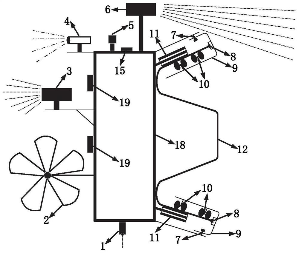
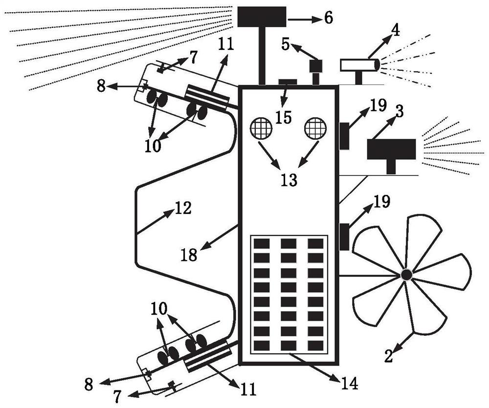
[0039] In one or more embodiments, an inspection robot for measuring road surface roughness is disclosed, referring to Figure 1-3 , including traveling devices, detection devices, fixing devices, power supply devices, early warning devices, positioning devices and warning devices.

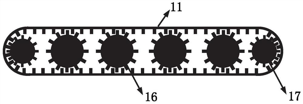
[0040] Such as figure 1 with figure 2 As shown, the fixing device is composed of an L-shaped fixed plate 9, a fixed plate directional wheel 8, and a fixed plate universal wheel 10. In order to link the L-shaped fixed plate 9 with the main body 18 of the inspection robot, the two are fixed by rivets 7 together. The L-shaped fixed plate 9 is anti-hooked on the upper and lower sides of the corrugated guardrail, and the L-shaped fixed plate 9 is respectively connected with the fixed plate directional wheel 8 and the fixed plate universal wheel 10;

[0041] The role of the fixed plate is exactly to fix the inspection robot on the guardrail; the role of the fixed plate directional wheel 8 is to driv...

Embodiment 2

[0056] In one or more embodiments, an inspection method of an inspection robot for measuring road surface smoothness is disclosed, including:

[0057] Trial run and calibration of various sensors on the inspection robot to ensure that it can work normally for a long time.

[0058] The inspection robot device is installed on the roadside wave guardrail 12 to ensure that the fixing device, the traveling device and the wave guardrail 12 are closely attached.

[0059] After the inspection robot collects data and completes the scheduled mileage collection work, extract the data for processing and analysis, complete road leveling and slope data collection, and road quality assessment;

[0060] Specifically, control the inspection robot to move along the road guardrail;

[0061] Obtain road surface data in the form of surface units through the first multi-beam laser radar 3, and obtain the real coordinates of the data through coordinate conversion;

[0062] By calculating the mean ...


PUM


Abstract

The invention discloses an inspection robot and an inspection method for measuring road surface smoothness, comprising: a robot body, the robot body is fixed on a road guardrail through a fixing device, and can move along the guard rail; The robot body is respectively provided with a first multi-beam laser radar and a first camera device facing the side of the road; the first multi-beam laser radar can perform multi-beam scanning on the road surface to form road surface data in the form of surface units. The camera device simultaneously records the multi-beam lidar detection area. The invention adopts the robot inspection mode to measure the smoothness of the road surface and monitor the side slope of the road at the same time, which can realize all-weather measurement, adapt to harsh environments, and avoid fatigue.

Description

technical field [0001] The invention relates to the technical field of road surface smoothness detection, in particular to an inspection robot and method for measuring road surface smoothness. Background technique [0002] The statements in this section merely provide background information related to the present invention and do not necessarily constitute prior art. [0003] Roughness refers to the measurement of the unevenness of the road surface within the specified standard indicators, which is an important indicator to measure the quality and service level of road construction. The quality of road flatness affects the service life of the road, the loss of transport vehicles, transportation costs and transportation safety, etc., and the road slope is also an important factor affecting the quality of the road, so how to quickly, effectively and accurately measure the road surface roughness And monitoring road slope has become a very meaningful topic nowadays. [0004] E...

Claims


Application Information

Patent Timeline
Patent Type & Authority Patents(China)
IPC IPC(8): G01B11/30G01C9/00
CPCG01B11/30G01C9/00
Inventor 吴建清皮任东孙仁娟吕琛朱新远张涵张宏博张洪智葛智管延华宋修广
Owner SHANDONG UNIV
Why Eureka
Try Eureka