
A monitoring device and monitoring method for deformation points of steel components

A technology for monitoring devices and steel components, applied to measuring devices, instruments, etc., can solve the problems of difficult placement of prisms, various structural forms, and variable measurement angles, and achieve the effects of improving monitoring accuracy and efficiency, quick installation, and convenient operation

Active Publication Date: 2021-08-24
BEIJING CONSTR ENG GRP CO LTD
View PDF0 Cites 0 Cited by
  • Summary
  • Abstract
  • Description
  • Claims
  • Application Information

AI Technical Summary

Problems solved by technology

[0004] When using ordinary prisms for deformation monitoring, due to the difficulty in placing the prisms at the deformation monitoring point, it is necessary to pre-weld the prism installation base on the steel components before splicing and positioning the steel components, which will cause structural damage to the steel components. Destroy the shape of the steel member
When using a special target patch to measure the accuracy, the measurement accuracy will be reduced by 50%, and the special target patch cannot be used on round steel members
At the same time, the structural forms of complex steel structure projects are diverse, and the measurement angles are changeable. Ordinary prisms cannot meet the requirements of angle transformation.

Method used


Image

  • A monitoring device and monitoring method for deformation points of steel components
  • A monitoring device and monitoring method for deformation points of steel components
  • A monitoring device and monitoring method for deformation points of steel components

Examples


Embodiment 1

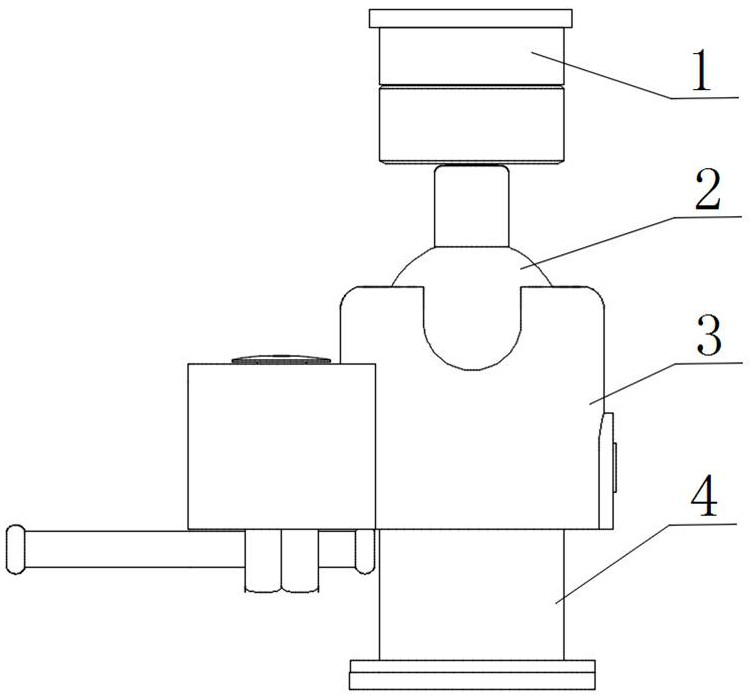
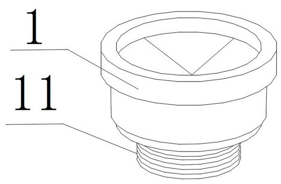
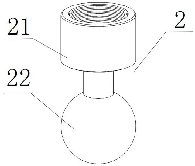
[0031] The invention provides a monitoring device for deformation points of steel components. The monitoring device for deformation points of steel components is used in conjunction with a total station for measuring base stations, such as Figure 1-8 As shown, the monitoring device for the deformation point of the steel member includes: a prism lens 1 , a cardan shaft head 2 , a clamp 3 and a base 4 . The universal shaft head 2 includes an adapter 21 and a rotating shaft head 22. One end of the rotating shaft head 22 is a spherical structure, and the other end is a cylindrical structure. The cylindrical structure is fixedly connected. The upper end inside the clamp 3 is a hollow structure matched with the spherical structure. The spherical structure is set in the hollow structure. One end of the base 4 is set inside the clamp 3 and connected with the spherical structure. The other end of the base 4 is magnetic. structure, adsorbed on the steel member.

[0032]In a preferred...

Embodiment 2

[0038] The invention provides a method for monitoring the deformation point of a steel component using a monitoring device for the deformation point of a steel component. The method for monitoring the deformation point of a steel component includes the following steps: It is installed in the hollow structure where the upper end of the clip body 31 matches with the spherical structure. Set one end of the adapter tube 41 inside the hoop body 31, and connect it with the spherical structure, and fix the adapter tube 41 and the right side of the hoop body 31 through the positioning screw 32, and through the locking screw 33 and the locking nut 34 fix the left side of the adapter tube 41 and the clamp body 31, and install the locking handle 35 on the locking nut 34. Install the adapter 21 of the universal shaft head 2 on the rotating shaft head 22 , and install the prism lens 1 on the upper end of the adapter 21 . The first base 42 is installed on the lower end of the adapter tube ...

Embodiment 3

[0042] Introduce the specific process of the monitoring method of the steel component deformation point of a preferred embodiment of the present invention below:

[0043] Firstly, the spherical structure of the rotating shaft head 22 in the universal shaft head 2 is installed in the hollow structure where the upper end of the clamp body 31 fits with the spherical structure. Set one end of the adapter tube 41 inside the hoop body 31, and connect it with the spherical structure, and fix the adapter tube 41 and the right side of the hoop body 31 through the positioning screw 32, and through the locking screw 33 and the locking nut 34 fix the left side of the adapter tube 41 and the clamp body 31, and install the locking handle 35 on the locking nut 34. Install the adapter 21 of the universal shaft head 2 on the rotating shaft head 22 , and install the prism lens 1 on the upper end of the adapter 21 . The first base 42 is installed on the lower end of the adapter tube 41, the sec...


PUM


Abstract

The invention provides a monitoring device and monitoring method for deformation points of steel components. The monitoring device for deformation points of steel components is used in conjunction with a total station for measuring base stations. The monitoring device for deformation points of steel components includes: Prism lenses, cardan heads, clamps and mounts. The universal shaft head includes an adapter and a rotating shaft head. One end of the rotating shaft head is a spherical structure, and the other end is a cylindrical structure. The upper end of the adapter is fixedly connected with the prism lens, and the lower end of the adapter is fixedly connected with the cylindrical structure; The upper end inside the hoop is a hollow structure matched with the spherical structure. The spherical structure is set in the hollow structure. One end of the base is set inside the hoop and connected with the spherical structure. The other end of the base is a magnetic structure, which is adsorbed on the steel on the component. The universal shaft head of the spherical structure of the present invention can rotate 360°, which improves the monitoring accuracy and efficiency, and the base of the magnetic structure avoids structural damage and appearance damage caused by steel components.

Description

technical field [0001] The invention relates to the technical field of deformation measurement and positioning of steel components, in particular to a monitoring device and a monitoring method for deformation points of steel components. Background technique [0002] Due to its short construction period, small structural section, light weight and good seismic performance, steel structure engineering has developed rapidly in my country. This makes the monitoring of steel structure deformation more and more important, which directly affects the safety of the building itself and the safety of people's lives and properties. [0003] At present, domestic steel structure building deformation monitoring methods often use: precision triangulation method, distance or angle intersection method, total station polar coordinate method and GPS method, etc. In the deformation monitoring of large-span complex steel structure engineering, the polar coordinate measurement of total station com...

Claims


Application Information

Patent Timeline
Patent Type & Authority Patents(China)
IPC IPC(8): G01B21/32
CPCG01B21/32
Inventor 李建功吴良良付雅娣闫天伟张晓煜周昊白晋合唐娜任泉曹永贝刘书安冯天力赵振鑫朱丹江刘博有刘钊
Owner BEIJING CONSTR ENG GRP CO LTD
Learn More