PCBA automatic test fixture

An automatic testing and jig technology, applied in the field of gluing machines, can solve the problems of inability to perform optical testing and low testing efficiency, and achieve the effects of improving testing accuracy, increasing testing items, and stabilizing position parameter calibration.

Pending Publication Date: 2021-03-16
武汉建谷精密机械科技有限公司
View PDF2 Cites 1 Cited by
  • Summary
  • Abstract
  • Description
  • Claims
  • Application Information

AI Technical Summary

Problems solved by technology

[0004] The areas covered by PCBA test fixtures include PCBA test machines, PCBA fixtures, PCBA test components, etc. The entire test fixture covers the entire process of PCBA testing. Now when testing, manual handling and manual testing are performed, and the test efficiency is low. At the same time, optical inspection cannot be performed during the inspection process, and optical inspection needs to be moved to other stations for inspection

Method used


Image

  • PCBA automatic test fixture
  • PCBA automatic test fixture
  • PCBA automatic test fixture

Examples


Embodiment 1

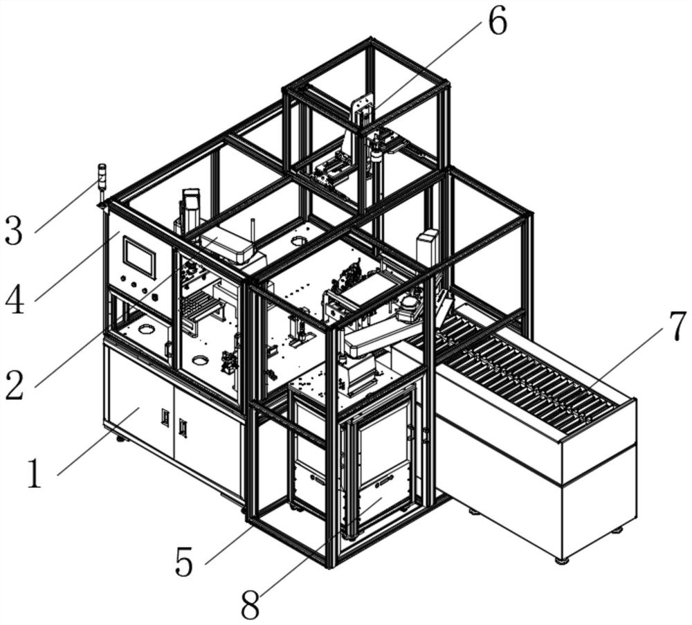
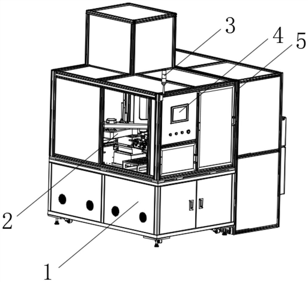
[0032] refer to Figure 1-7, a PCBA automatic test fixture, including a test equipment main body 1 and a detection table 10 installed in the middle of the inner cavity of the test equipment main body 1, a raw material support 12 is fixedly installed on the edge of the detection table 10, and a test equipment main body 1 is provided with a The main body frame 5, the top horizontal position of the main frame 5 is bolted and fixed with the test assembly 6, the side of the test equipment main body 1 is provided with a discharge track 7, the discharge track 7 adopts a chain plate track, and the chain plate surface of the discharge track 7 Through holes are evenly opened on the top, and the discharge track 7 is provided with a push-out telescopic rod at the plane projection position of the discharge assembly 8. The top corner of the main frame 5 is vertically fitted and fixed with an indicator light 3, and the front of the main frame 5 is fitted There is a control host 4, a feeding ...

Embodiment 2

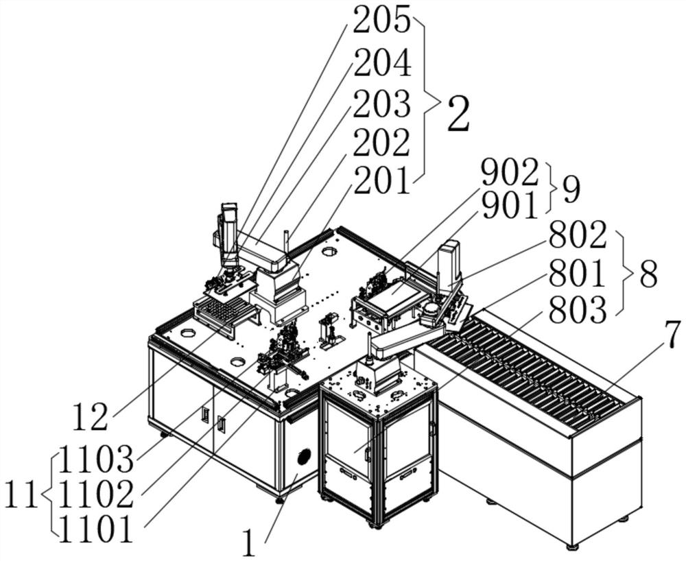
[0039] refer to figure 2 The feeding assembly 2 of a PCBA automatic test fixture includes a main body bracket 201 that is bolted and fixed to the surface of the detection table 10. The top of the main body bracket 201 is pivotally connected with a main body rotating frame 203, and the end of the main body rotating frame 203 is axially connected with a The positioning support arm 206, the end of the positioning support arm 206 is pivotally connected with the shifting end 204, the end of the shifting end 204 is connected with the feeding jaw 205, and the side of the main body support 201 is vertically equipped with a detection tube 202 for detecting The tube 202 is integrated with position, acceleration, and angle sensors. The top of the detection tube 202 is fitted with the physical origin of the detection device. The main body rotating frame 203 and the positioning support arm 206 are all made of aluminum alloy sheet metal. The main body rotating frame 203 and the positioning ...

Embodiment 3

[0042] refer to Figure 7 A test assembly 6 of a PCBA automatic test fixture includes a longitudinal slide rail 601 that is bolted and fixed to the main body frame 5. The top of the longitudinal slide rail 601 is vertically provided with a horizontal slide rail 603. The longitudinal slide rail 601 and the horizontal slide rail A sliding platform 602 is arranged between the rails 603, and the top of the horizontal sliding rail 603 is slidably connected with a horizontal sliding platform 604, and the middle part of the top surface of the horizontal sliding platform 604 is fixed with a micro-motion sliding rail 610, and the middle part of the micro-motion sliding rail 610 is provided with an auxiliary Reinforcing rib 609, the front of auxiliary reinforcing rib 609 is bolted and fixed with vertical slide rail 608, and the front of vertical slide rail 608 is provided with detection sensor 606, and electric appliance is fixed between detection sensor 606 and the slide table of vertic...


PUM


Abstract

The invention provides a PCBA automatic test fixture which comprises a test equipment body and a detection table top installed in the middle of an inner cavity of the test equipment body. A raw material support is fixedly installed on the edge of the detection table top, a body frame is arranged on the outer edge of the test equipment body, a test assembly is bolted and fixed to the horizontal position of the top of the body frame, a discharging track is arranged on the side face of the test equipment body in a penetrating mode, an indication signal lamp is vertically embedded and fixed to thecorner of the top of the body frame, and a control host is embedded in the front face of the body frame. A PCBA board is detected through a test assembly installed at the top, the test assembly can adjust spatial position change, micro adjustment can be achieved in the whole adjustment process, and it is guaranteed that the whole equipment has good detection position changes. Meanwhile, an adjustable detection assembly at the top can achieve optical detection on the surface of a PCBA board to be detected, detection items are increased, data measurement and calculation of PCBA board surface detection are guaranteed, and the detection accuracy is improved.

Description

technical field [0001] The invention relates to the technical field of gluing machines, in particular to a PCBA automatic test fixture. Background technique [0002] The Chinese patent number is CN211627635U Color Doppler Ultrasound Control Module PCBA Wire Harness Automatic Test Fixture. A cantilever beam is fixed on the test box. The middle part of the cantilever beam is horizontally fixed on the carrier plate. There are positioning pins on both sides, a limit pin is provided on one inner wall of the receiving tank, and a positioning screw for positioning the product to be tested is provided on the solid bottom of the receiving tank, a guide column is erected and fixed on the side of the carrier plate, and the upper platen box is placed on the On the guide column, a test needle board is installed on the bottom surface of the upper platen box, and test probes are distributed on the test needle board. A support is installed on the top of the cantilever beam, and the movement...

Claims


Application Information

Patent Timeline
Patent Type & Authority Applications(China)
IPC IPC(8): G01R31/28
CPCG01R31/28
Inventor 宁红伟
Owner 武汉建谷精密机械科技有限公司
Why Eureka
Try Eureka