
Hybrid excitation brushless direct-current motor

A brushed DC motor and hybrid excitation technology, applied in the direction of magnetic circuits, electromechanical devices, electrical components, etc., can solve the problems of weak magnetic force of the magnet inside the motor, difficult inspection and maintenance of the internal parts of the motor, complex structure, etc.

Inactive Publication Date: 2021-03-16
SUMEC HARDWARE & TOOLS
View PDF6 Cites 0 Cited by
  • Summary
  • Abstract
  • Description
  • Claims
  • Application Information

AI Technical Summary

Problems solved by technology

[0003] At present, there are big problems in the installation of the fixed magnets used in the existing hybrid excitation motors on the market, and in the auxiliary rotation of the drive shaft to the rotor. During the use of the existing hybrid excitation motors, the internal temperature of the motor will gradually increase. Too high will lead to the weakening of the magnetic force of the magnet inside the motor, which will lead to a decrease in the working efficiency of the motor. At the same time, the rotation of the hybrid excitation motor depends on the shaft for force support. During the long-term operation of the existing motor shaft, the frictional resistance of the shaft In addition, the internal structure of the existing hybrid excitation motor is complicated, and most of the components are fixedly connected. Once the motor fails, it is difficult for the operator to inspect and repair the internal components of the motor. To this end we propose a hybrid excitation brushless DC motor

Method used


Image

  • Hybrid excitation brushless direct-current motor
  • Hybrid excitation brushless direct-current motor
  • Hybrid excitation brushless direct-current motor

Examples


Embodiment Construction

[0026] The following will clearly and completely describe the technical solutions in the embodiments of the present invention with reference to the accompanying drawings in the embodiments of the present invention. Obviously, the described embodiments are only some, not all, embodiments of the present invention.

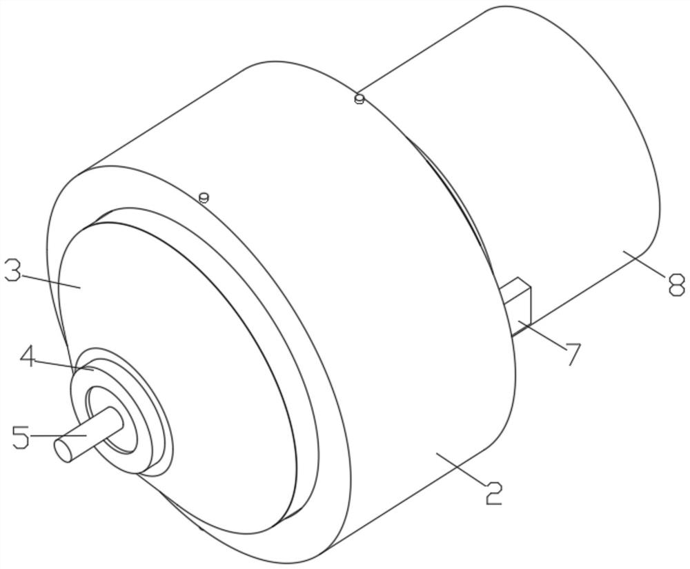
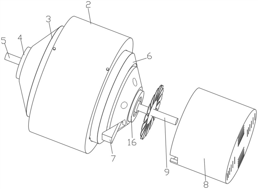
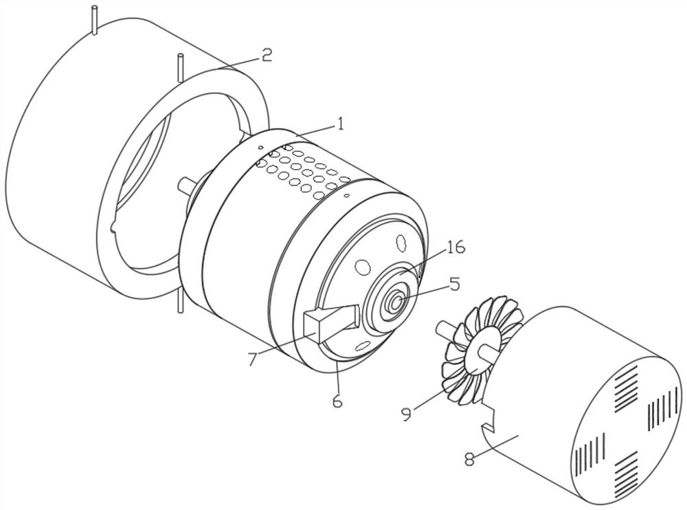
[0027] see Figure 1 to Figure 8, the present invention provides a technical solution: a hybrid excitation brushless DC motor, including a motor middle cover 1, the two sides of the motor middle cover 1 are provided with symmetrically distributed dense circular holes, and the outer sides of the motor middle cover 1 are opened There is an inwardly recessed annular notch, and the inside of the motor front cover 3 and the motor rear cover 6 is provided with a stepped annular notch, and the annular notches at both ends of the motor middle cover 1 are aligned with the motor front cover 3 and the motor rear cover 6. The internal stepped annular notches are adapted to each ...


PUM


Abstract

The invention discloses a hybrid excitation brushless direct-current motor, belonging to the technical field of motors. The hybrid excitation brushless direct current motor comprises a motor middle cover, wherein a motor front cover is movably connected to one side of the outer portion of the motor middle cover; a heat-dissipating outer shell is movably connected to the outer portion of the motorfront cover; one side of the exterior of the motor front cover is fixedly connected with a front-end rolling shaft; and the interior of the front-end rolling shaft is fixedly connected with a rotatingshaft. According to the hybrid excitation brushless direct-current motor, the outer side of the motor rear cover is fixedly connected with a heat-dissipating outer box, the tail end of the rotating shaft is fixedly connected with a heat-dissipating piece; the two sides of the outer portion of the motor middle cover are provided with the evenly-distributed circular groove holes, and meanwhile, theouter portion of the motor front cover and the outer portion of the motor rear cover are movably connected with the heat-dissipating outer shell; and two through holes are formed in the outer side ofthe heat-dissipating outer shell, so high temperature in the motor middle cover can be rapidly discharged in the operation process of the device.

Description

technical field [0001] The invention relates to the technical field of motors, in particular to a hybrid excitation brushless DC motor. Background technique [0002] The hybrid excitation motor is a wide speed-regulating motor, which combines the advantages of the permanent magnet synchronous motor and the electric excitation synchronous motor. The wind power generation system and drive system of the hybrid excitation motor within the range of speed operation has a bright and mining application prospect, especially It is in the current society that all kinds of electromechanical products and automobiles have begun to get involved in hybrid excitation motors. Therefore, in order to meet the needs of current machinery, a hybrid excitation brushless DC motor is needed. [0003] At present, there are big problems in the installation of the fixed magnets used in the existing hybrid excitation motors on the market, and in the auxiliary rotation of the drive shaft to the rotor. Dur...

Claims


Application Information

Patent Timeline
IPC IPC(8): H02K5/20H02K9/06H02K5/173H02K1/24H02K1/30H02K1/17H02K1/18H02K29/00
CPCH02K1/17H02K1/185H02K1/24H02K1/30H02K5/1732H02K5/20H02K9/06H02K29/00H02K2205/09
Inventor 刘楷林有余吴玉华周国扬
Owner SUMEC HARDWARE & TOOLS
Learn More