Electronic component selective wave soldering equipment and soldering method thereof

A technology for wave soldering and electronic components, which is applied in the field of selective wave soldering of electronic components and its welding field, can solve the problems of inconvenient material fixing, inconvenient protection of electronic components, and inconvenience in internal insulation of the device, etc., so as to reduce energy consumption and increase usability. , the effect of easy thermal insulation

Pending Publication Date: 2021-03-19
彼勒豪斯(苏州)自动焊锡系统有限公司
View PDF10 Cites 0 Cited by
  • Summary
  • Abstract
  • Description
  • Claims
  • Application Information

AI Technical Summary

Problems solved by technology

[0004] However, the selective wave soldering equipment for electronic components and its welding method provided in the above technical solution still have many disadvantages in actual use. It is not convenient to heat the inside of the device, and it is not convenient to replace the spot welding nozzle of the device. It is not convenient to fix the material, it is not convenient to protect the electronic components, and it is not convenient to solder different electronic components

Method used


Image

  • Electronic component selective wave soldering equipment and soldering method thereof
  • Electronic component selective wave soldering equipment and soldering method thereof
  • Electronic component selective wave soldering equipment and soldering method thereof

Examples


Embodiment Construction

[0034] The following will clearly and completely describe the technical solutions in the embodiments of the present invention with reference to the accompanying drawings in the embodiments of the present invention. Obviously, the described embodiments are only some, not all, embodiments of the present invention. Based on the embodiments of the present invention, all other embodiments obtained by persons of ordinary skill in the art without making creative efforts belong to the protection scope of the present invention.

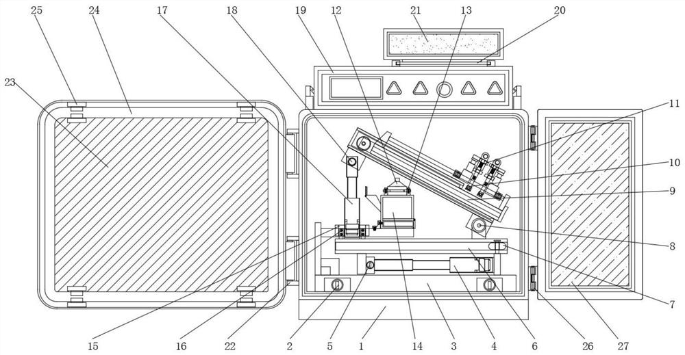
[0035] according to Figure 1-6The shown selective wave soldering equipment for electronic components includes a container fresh-keeping box 1, a second rotating rod 22 and a third rotating rod 26, the inner side of the wave soldering machine 1 is connected with a first positioning rod 2, and the first The outer screw of the positioning rod 2 is connected with the base 3, and the first electric push rod 4 is installed above the base 3, and one end screw of the...


PUM


Abstract

The invention discloses electronic element selective wave soldering equipment and a soldering method thereof and particularly relates to the technical field of electronic element processing. The electronic element selective wave soldering equipment comprises a container fresh-keeping box, second rotating rods and third rotating rods; the inner side of a wave soldering machine is in screw connection with first positioning rods; the outer side of each first positioning rod is in screw connection with a base; a first electric push rod is installed above the base; one end of the first electric push rod is in screw connection with a second positioning rod; the outer side of the second positioning rod is in screw connection with a sliding rail; the inner side of the sliding rail abuts against apulley; a first rotating shaft is installed above the pulley; a storage mechanism is installed on the outer side of the first rotating shaft; and an anti-abrasion mechanism is mounted above the storage mechanism. According to the electronic element selective wave soldering equipment and the soldering method thereof, heat insulation cotton is tightly attached through a sealing cover, when the equipment is used, the arrangement of the heat insulation cotton facilitates heat preservation of the interior of the equipment, the usability of the equipment is improved, and the energy consumption of the equipment is reduced.

Description

technical field [0001] The present invention relates to the technical field of electronic components, and more specifically, the present invention relates to a selective wave soldering equipment for electronic components and a soldering method thereof. Background technique [0002] Electronic components are the basic elements in electronic circuits, usually individually packaged, and have two or more leads or metal contacts. Electronic components must be connected to each other to form an electronic circuit with specific functions, such as amplifiers, radio receivers, Oscillators, etc., one of the common ways to connect electronic components is soldering to a printed circuit board. Selective wave soldering is divided into two types: offline selective wave soldering and online selective wave soldering. Offline selective wave soldering, offline The type refers to the way of being offline with the production line. The flux spraying machine and the selective welding machine are ...

Claims


Application Information

Patent Timeline
Patent Type & Authority Applications(China)
IPC IPC(8): B23K3/00B23K3/08B23K37/04B23K1/08
CPCB23K3/00B23K3/087B23K3/08B23K1/085
Inventor 达仁韦恩·哈维
Owner 彼勒豪斯(苏州)自动焊锡系统有限公司
Why Eureka
Try Eureka