
Automobile brake disc drilling center

A technology for automobile braking and drilling, which is applied in the directions of boring/drilling, drilling/drilling equipment, maintenance and safety accessories, etc. It can solve the problem of chaotic workbench, easy scattering of debris, and affecting the health of operators, etc. problem, achieve the effect of reducing the replacement cycle and reducing the dust removal pressure

Inactive Publication Date: 2021-03-19
徐保龙
View PDF0 Cites 2 Cited by
  • Summary
  • Abstract
  • Description
  • Claims
  • Application Information

AI Technical Summary

Problems solved by technology

The brake caliper clamps the brake disc to generate braking force. When the brake is stepped on, it clamps the brake disc to slow down or stop the car. Brakes include disc brakes, drum brakes and air brakes, because disc brakes dissipate more heat than drum brakes. Well, under the high-speed braking state, it is not easy to produce thermal fading, so its high-speed braking effect is good, so most of the cars now use disc brakes, while ordinary brake discs are usually made of forged steel or gray cast iron. Manufacturing, and a large number of cutting and drilling operations are required in the production process, while the structure of the traditional automobile brake disc drilling center is relatively simple, and the drilling center will produce processing dust and metal debris during processing, and the dust Not only will it affect the health of the operators, but also the debris formed by the cutting process is easy to scatter around, which not only makes the workbench more chaotic, but also cumbersome to clean up the scattered metal debris after the work is over

Method used


Image

  • Automobile brake disc drilling center
  • Automobile brake disc drilling center
  • Automobile brake disc drilling center

Examples


Embodiment Construction

[0022] The following will clearly and completely describe the technical solutions in the embodiments of the present invention with reference to the accompanying drawings in the embodiments of the present invention. Obviously, the described embodiments are only some, not all, embodiments of the present invention. Based on the embodiments of the present invention, all other embodiments obtained by persons of ordinary skill in the art without making creative efforts belong to the protection scope of the present invention.

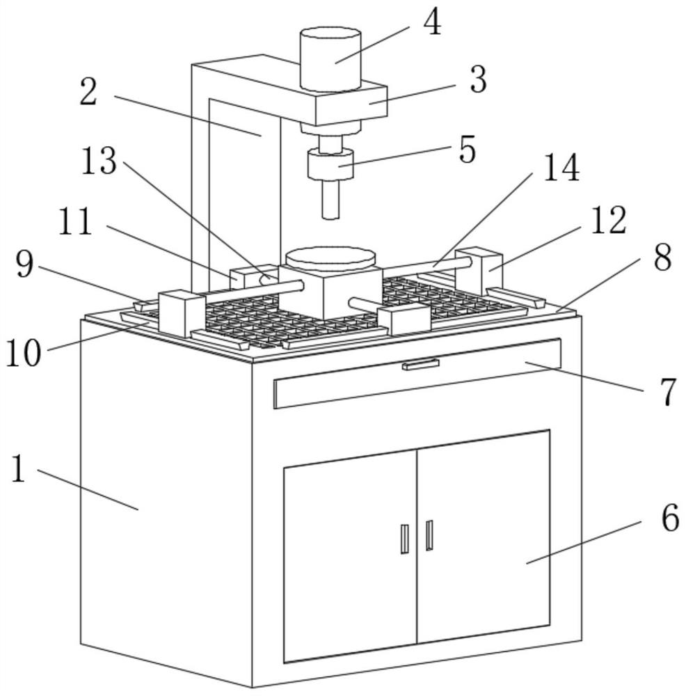
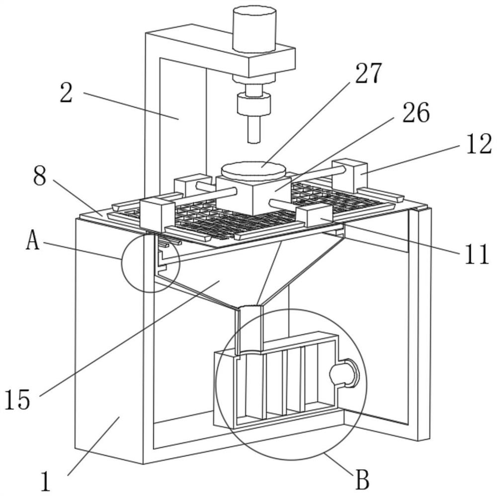
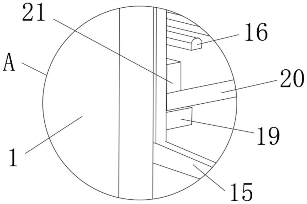
[0023] see Figure 1-5 , the present invention provides a technical solution: a drilling center for automobile brake discs, including an operating table 1 and a support rod 2 arranged on the back of the operating table 1, the operating table 1 is a rectangular box, and the front surface of the box is opened There are a first notch and a second notch, and a door 6 is installed through a hinge in the first notch, and a sealing plate 7 is installed in the second ...


PUM


Abstract

The invention discloses an automobile brake disc drilling center. The automobile brake disc drilling center comprises an operation table and a supporting rod arranged on the back face of the operationtable, wherein the operation table is a rectangular box body; a first notch and a second notch are arranged in the front surface of the box body; a box door is arranged in the first notch through a hinge; a sealing plate is rotatably arranged in the second notch through a hinge; handle structures are arranged on the box door and the sealing plate; the upper surface of the operation table is not closed; a mesh plate is erected on the upper surface of the operation table; and mesh structures are evenly arranged in the center of the mesh plate. The mesh plate is arranged on the upper surface ofthe operation table, a waste hopper is arranged at the lower end of the mesh plate, an outlet in the lower end of the waste hopper is connected to an air inlet of a dust removal box, and an exhaust port of the dust removal box is connected to the air inlet end of an air pump through a second air pipe, so that adsorption force is formed on the upper surface of the operation table through the actionof the air pump, and therefore, the situation that the physical health of workers is affected due to random drifting of dust formed by drilling machining is avoided.

Description

technical field [0001] The invention relates to the related technical field of brake disc production, in particular to an automobile brake disc drilling center. Background technique [0002] The brake disc, in simple terms, is a round disc that rotates when the car is moving. The brake caliper clamps the brake disc to generate braking force. When the brake is stepped on, it clamps the brake disc to slow down or stop the car. Brakes include disc brakes, drum brakes and air brakes, because disc brakes dissipate more heat than drum brakes. Well, under the high-speed braking state, it is not easy to produce thermal fading, so its high-speed braking effect is good, so most of the cars now use disc brakes, while ordinary brake discs are usually made of forged steel or gray cast iron. Manufacturing, and a large number of cutting and drilling operations are required in the production process, while the structure of the traditional automobile brake disc drilling center is relatively...

Claims


Application Information

Patent Timeline
Patent Type & Authority Applications(China)
IPC IPC(8): B23Q11/00B23B41/00
CPCB23B41/00B23Q11/0046
Inventor 不公告发明人
Owner 徐保龙
Learn More