Automatic edge grinding device for iron box
An automatic and edging technology, applied in the direction of grinding drive device, machine tool suitable for grinding the edge of workpiece, grinding machine, etc., can solve the problems of low production efficiency, waste of time and manpower, unable to grind the edge of the iron box well, etc. Achieve the effect of reducing work intensity, improving accuracy and speeding up
- Summary
- Abstract
- Description
- Claims
- Application Information
AI Technical Summary
Problems solved by technology
Method used
Image

Examples
Embodiment 1
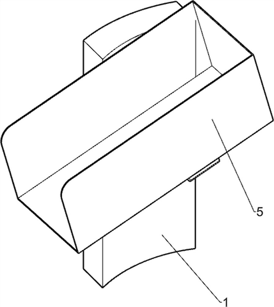
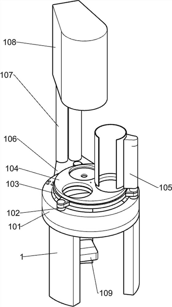
[0072] An automatic edging device for iron boxes, such as Figure 1-10 Shown, comprise support plate one 1, support ring 101, fixed column 102, fixed plate 103, turntable one 104, discharge box 105, fixed block one 106, support column 107, support block 108, support plate two 109, slide Rail 5, fixed block 3 501, support plate 4 502, power mechanism, edging mechanism, fixing mechanism and clamping mechanism, three support plates 1 are distributed in an array, and support ring 101 is fixedly connected to the upper end of support plate 1, Three fixed columns 102 are distributed in an array around the upper part of the support ring 101, the fixed plate 103 is fixedly installed between the upper parts of the three fixed columns 102, the turntable one 104 is installed in the middle of the upper part of the fixed plate 103 in rotation, and the discharge box 105 is fixedly installed on On a fixed column 102 on the right side, the discharge box 105 is located above the turntable one 1...
Embodiment 2
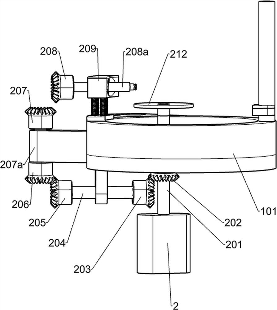
[0075] On the basis of Example 1, such as Figure 3-8 As shown, the edging mechanism includes a motor one 2, a first shaft 201, a first bevel gear 202, a second shaft 204, a second bevel gear 203, a third bevel gear 205, a connecting plate 207a, a fourth bevel gear 206, the fifth bevel gear 207, the second fixed block 210, the first spring 211, the first slide block 209, the third shaft rod 208a, the sixth bevel gear 208 and the second turntable 212, the first motor 2 is fixedly installed on the top of the second support plate 109, The lower end of the first shaft 201 is fixedly installed on the output shaft of the motor one 2, the upper end of the first shaft 201 runs through the fixed plate 103, the first bevel gear 202 is fixedly installed on the lower side of the first shaft 201, and the second shaft Rod 204 is rotatably installed on the lower left side of support ring 101, second bevel gear 203 is affixed to the right end of second shaft rod 204, second bevel gear 203 mes...
Embodiment 3
[0082] On the basis of Example 2, such as Figure 6 As shown, the locking mechanism includes a push post 305, a spring 2 306 and a push bead 307, the push post 305 is fixedly installed on the lower left side of the fixed plate 103, the spring 2 306 is sleeved on the push post 305, and the spring 2 306 is located on the fixed plate 103 Between the first turntable and the first turntable 104, the top bead 307 is fixedly installed on the upper end of the second spring 306, and the top bead 307 cooperates with the first turntable 104.
[0083] The lower side of the turntable 104 is provided with a draw-in slot. When the turntable 104 rotates to the position below each mechanism, it is necessary to stop the rotation of the turntable 104 due to inertia. The action of the spring 2 306 drives the top ball 307 into the slot of the turntable 104, and temporarily fixes the turntable 104. When the turntable 104 continues to move, the top ball 307 slides out of the slot, and the spring 2 3...
PUM
 Abstract
Description
Claims
Application Information
 - R&D
- Intellectual Property
- Life Sciences
- Materials
- Tech Scout
- Unparalleled Data Quality
- Higher Quality Content
- 60% Fewer Hallucinations
Browse by: Latest US Patents, China's latest patents, Technical Efficacy Thesaurus, Application Domain, Technology Topic, Popular Technical Reports.
© 2025 PatSnap. All rights reserved.Legal|Privacy policy|Modern Slavery Act Transparency Statement|Sitemap|About US| Contact US: help@patsnap.com