
Supporting frame

A technology of support frame and support table, applied in the field of support frame, can solve the problems of being heavy, inconvenient to move, unable to meet the needs of welding or testing without dead ends, etc., and achieve the effect of ensuring safety and reliability and ensuring support strength.

Inactive Publication Date: 2021-03-19
DATONG ELECTRIC LOCOMOTIVE OF NCR
View PDF6 Cites 0 Cited by
  • Summary
  • Abstract
  • Description
  • Claims
  • Application Information

AI Technical Summary

Problems solved by technology

In the parts of electric locomotives, such as welding or non-destructive testing of transformers, car bodies and frames, due to the limitations of site location, flexibility of personnel operation, and space constraints of machine operation, it is impossible to meet all-round and no dead ends. Welding or inspection needs
Among them, in the existing welding or testing process, the supporting frame is used to support the parts of the electric locomotive. The existing supporting frame requires the operator to manually adjust and position when the parts are not supported, and the structure of the supporting frame is complex, heavy and inconvenient to move.

Method used


Image

  • Supporting frame
  • Supporting frame

Examples


Embodiment Construction

[0040] Typical embodiments embodying the features and advantages of the present invention will be described in detail in the following description. It should be understood that the present invention can have various changes in different embodiments without departing from the scope of the present invention, and that the description and drawings therein are illustrative in nature and not intended to limit the present invention. invention.

[0041] In the following description of various exemplary embodiments of the invention, reference is made to the accompanying drawings, which form a part hereof, and in which are shown by way of example different exemplary structures, systems, and embodiments in which aspects of the invention may be implemented and steps. It is to be understood that other specific arrangements of components, structures, exemplary devices, systems and steps may be utilized and structural and functional modifications may be made without departing from the scope...


PUM


Abstract

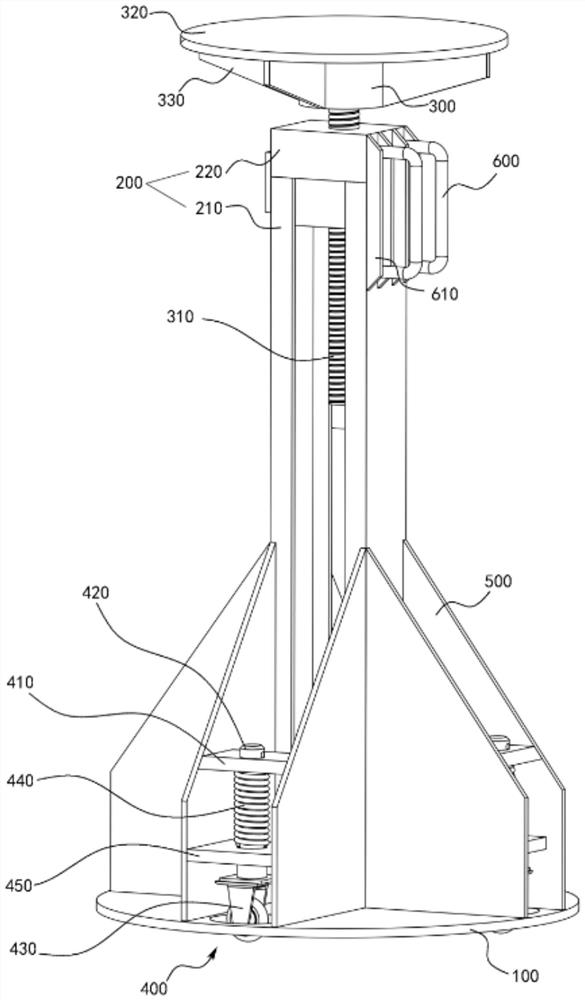
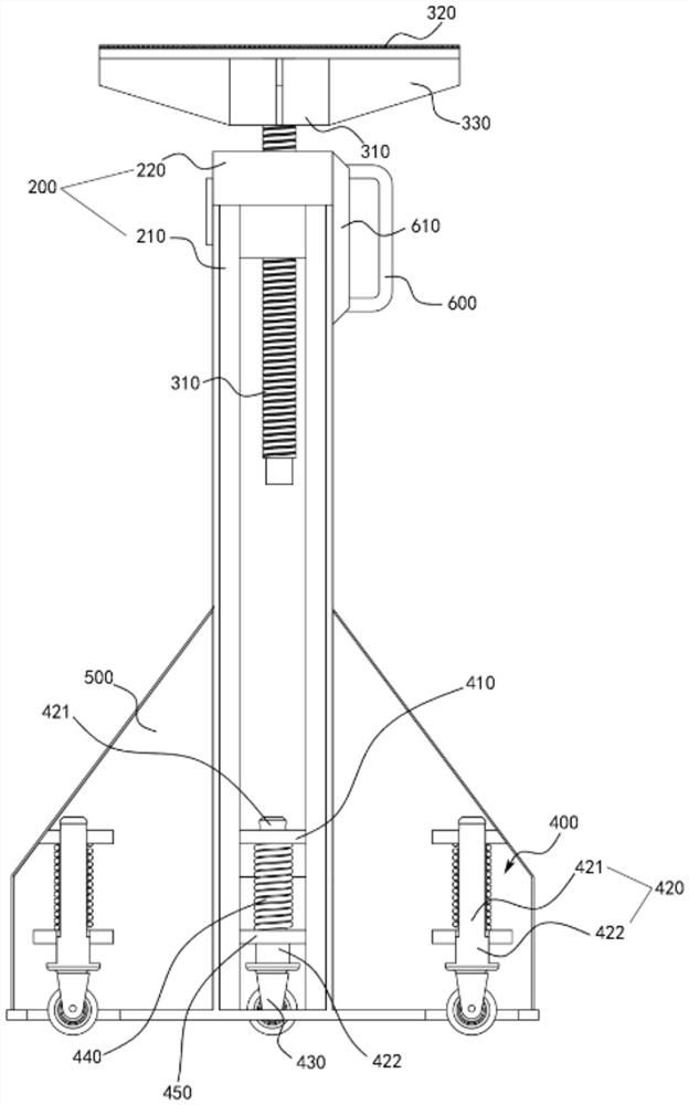
The invention provides a supporting frame. The supporting frame comprises a bottom plate, a vertical frame, a supporting table and a plurality of walking units, the vertical frame is vertically arranged on the bottom plate, a screw hole is formed in the top of the vertical frame, the supporting table is arranged above the vertical frame in a liftable mode and used for bearing a workpiece, and a screw rod is arranged at the bottom of the supporting table and is arranged in the screw hole in a penetrating mode, so that the supporting table is arranged at the top of the vertical frame in a liftable mode, each walking unit comprises a first limiting plate, a moving pin, a vehicle wheel and an elastic piece, the first limiting plates are arranged above the bottom plate and are provided with first through holes, the top ends of the moving pins are arranged in the first through holes in a penetrating mode, the vehicle wheels are arranged at the bottom ends of the moving pins, and the elasticpieces are connected between the bottom faces of the first limiting plates and the moving pins. When the supporting frame bears the workpiece, the elastic pieces are compressed by the gravity of the workpiece, the bottom plate makes contact with the ground, and when the weight of the workpiece disappears, the elastic pieces return to the initial state to jack the bottom plate, so that the bottom plate is higher than the bottoms of the vehicle wheels.

Description

technical field [0001] The invention relates to the technical field of rail vehicle parts processing and manufacturing, in particular to a support frame. Background technique [0002] Electric locomotives are the main traction power equipment in the railway transportation industry. In the parts of electric locomotives, such as welding or non-destructive testing of transformers, car bodies and frames, due to the limitations of the site location, the flexibility of personnel operations, and the space constraints of machine operation, it is impossible to meet all-round and no dead ends. Welding or inspection needs. Among them, in the existing welding or testing process, the supporting frame is used to support the parts of the electric locomotive. The existing supporting frame requires the operator to manually adjust and position when the parts are not supported, and the structure of the supporting frame is complex, heavy and inconvenient to move. Contents of the invention ...

Claims


Application Information

Patent Timeline
IPC IPC(8): B25H1/06B25H1/16B23K37/04
CPCB23K37/0461B25H1/06B25H1/16
Inventor 刘雁杰王军伟闫庆文
Owner DATONG ELECTRIC LOCOMOTIVE OF NCR
Learn More