Waste line peeling device for communication

A wire winding and leather tube technology, which is applied in the field of waste wire peeling devices for communication, can solve problems such as chaotic distribution of waste wires, inconvenient waste wire transportation, and difficulty in untwisting waste wires, so as to achieve uniform winding of waste wires, improve cost performance, The effect of improving quality

Inactive Publication Date: 2021-03-19
王洪明
View PDF0 Cites 2 Cited by
  • Summary
  • Abstract
  • Description
  • Claims
  • Application Information

AI Technical Summary

Problems solved by technology

[0003] After peeling the waste thread, the traditional waste thread peeling device will use the winding roller on the peeling device to wind the peeled waste thread to collect the waste thread, but the general waste thread peeling device It is difficult to control the winding position of the waste thread when winding the waste thread, which causes the uneven distribution of the waste thread when it is wound on the winding roller, which may make the distribution of the waste thread chaotic during winding, which may cause the waste thread to be wound when winding. It is always wound on the same position of the winding roller, which makes it difficult to untie the waste thread wound on the winding roller, which is inconvenient for the next step of processing the waste thread. At the same time, the traditional waste thread peeling device first peels off the The waste thread of the skin is wound on the thread winding roller of the peeling device, and then the waste thread on the thread winding roller is wound on other thread take-up devices, and then the waste thread is transported. The operation is more complicated and it is not convenient to carry out the waste thread transportation, and at the same time have an impact on the next step of processing waste wire

Method used


Image

  • Waste line peeling device for communication
  • Waste line peeling device for communication
  • Waste line peeling device for communication

Examples


Embodiment 1

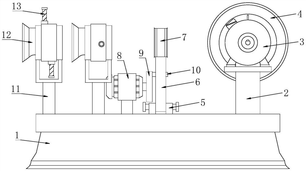
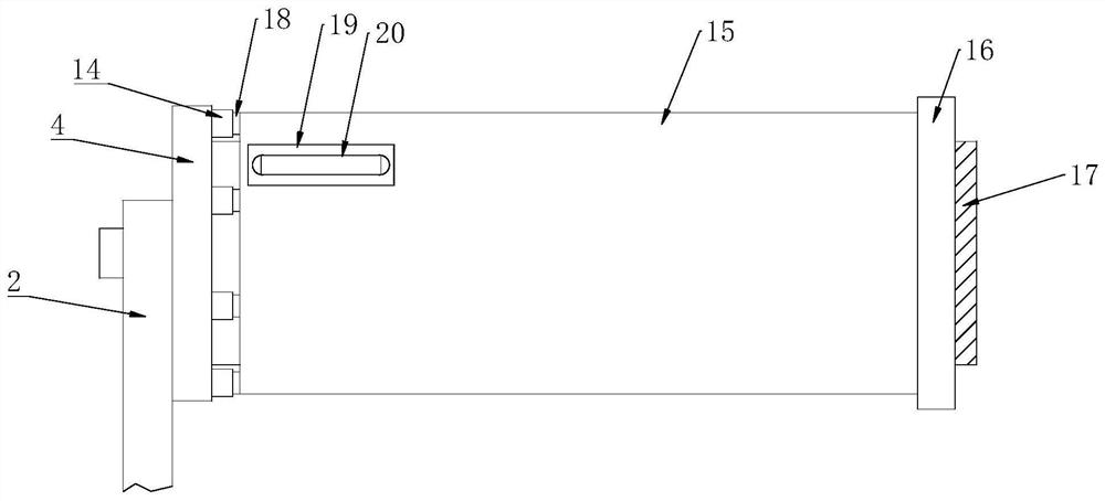
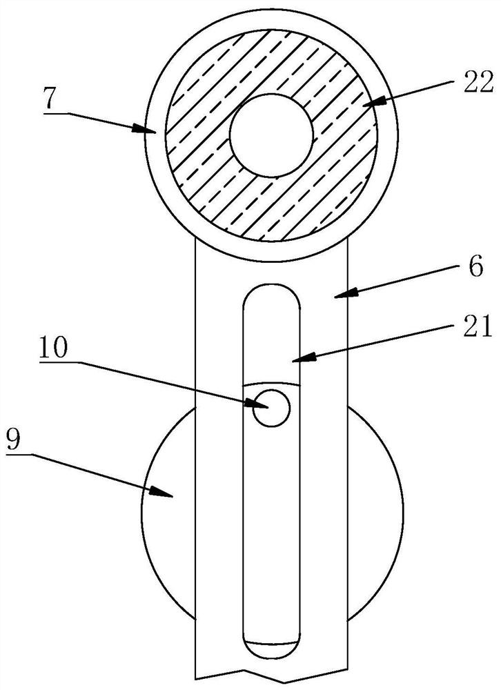
[0039] see Figure 1-10, a communication waste wire peeling device, comprising a base 1, a first mounting plate 2 is fixedly connected to the top of the base 1 near the right side, a first motor 3 is fixedly installed on the front of the first mounting plate 2, the first The output end of the motor 3 runs through the first mounting plate 2 and is fixedly connected with a retaining plate 4, the back of the retaining plate 4 is fixedly connected with a rotating roller 17, and the back of the retaining plate 4 is provided with inserting components at equal intervals near the outer position, The outer side of the turning roller 17 is movably connected with a winding roller 15, and the outer side of the winding roller 15 is provided with a wire fixing groove 19 near the front position, and the inner bottom of the wire fixing groove 19 is fixedly connected with a winding rod 20, and the winding rod 20 is in the shape of " U"-shaped structure, the depth of the fixing groove 19 is gre...


PUM


Abstract

The invention discloses a waste line peeling device for communication, and belongs to the technical field of communication waste line recovery. The waste line peeling device for communication comprises a base, a first mounting plate is fixedly connected to a position, close to the right side, of the top of the base, a first motor is fixedly mounted on the front face of the first mounting plate, the output end of the first motor penetrates through the first mounting plate and is fixedly connected with a retention plate, the back face of the retention plate is fixedly connected with a rotating roller, inserting and fixing assemblies are arranged at the positions, close to the outer side, of the back face of the retention plate at equal intervals, the outer side of the rotating roller is movably connected with a line winding roller, and line fixing groove is formed in the position, close to the front face, of the outer side of line winding roller. According to the waste line peeling device for communication, a guide ring can carry out control on the winding direction of waste lines, so that the waste lines are wound more uniformly, the waste lines are prevented from being wound at thesame position all the time during winding, the waste lines are orderly wound on the line winding roller, the situation that the waste lines wound on the line winding roller are difficult to unwind isavoided, and the waste lines can be conveniently treated in the next step.

Description

technical field [0001] The invention relates to the technical field of recycling waste communication wires, in particular to a peeling device for waste communication wires. Background technique [0002] The communication transmission line is a linear structure device that transmits electromagnetic energy. It is an important part of the telecommunication system. It is used to transport the electromagnetic wave carrying information from one point to another along the path specified by the transmission line. The transmission line is Materials necessary for communication. When the transmission line is discarded or aged, the transmission line needs to be recycled. In order to facilitate the recycling of the transmission line, the waste transmission line needs to be peeled. [0003] After peeling the waste thread, the traditional waste thread peeling device will use the winding roller on the peeling device to wind the peeled waste thread to collect the waste thread, but the genera...

Claims


Application Information

Patent Timeline
Patent Type & Authority Applications(China)
IPC IPC(8): B26D3/16B26D7/26B08B1/00B08B1/02B65H54/28B65H67/04
CPCB08B1/006B08B1/02B26D3/16B26D7/2628B65H54/2827B65H67/0411Y02P70/10
Inventor 王洪明
Owner 王洪明
Why Eureka
Try Eureka