Lifting appliance for crane

A spreader and crane technology, which is applied in the field of crane spreaders, can solve problems such as insufficient gripping force, rainwater corrosion, and small grabbing area, and achieve the effects of easy reinforcement and limitation, easy lifting, and convenient storage

Active Publication Date: 2021-03-19
ZHUHAI TIANLI HEAVY IND
View PDF6 Cites 0 Cited by
  • Summary
  • Abstract
  • Description
  • Claims
  • Application Information

AI Technical Summary

Problems solved by technology

[0003] In the course of realizing the present invention, the inventor finds that there are at least the following problems in the prior art that have not been resolved: 1. The hook body of the general spreader is a single hook body , when lifting large heavy objects, the area it grabs is small, and the gripping force is not large enough; When hoisting a large amount of steel coils, the steel coils may fall forward and backward due to the instability of the spreader; 3. According to the needs, the stacked heights of the steel coils are different. When the stacked height is too low, the restrictions on the steel coils 4. Cranes generally work outdoors. When it is rainy, rainwater will seep into the upper end of the crane through the connection between the upper end of the spreader and the steel cable of the crane. Rainwater accumulation will cause it to be cleaned up frequently. It will cause rainwater corrosion and affect lifting safety

Method used


Image

  • Lifting appliance for crane
  • Lifting appliance for crane
  • Lifting appliance for crane

Examples


Embodiment approach

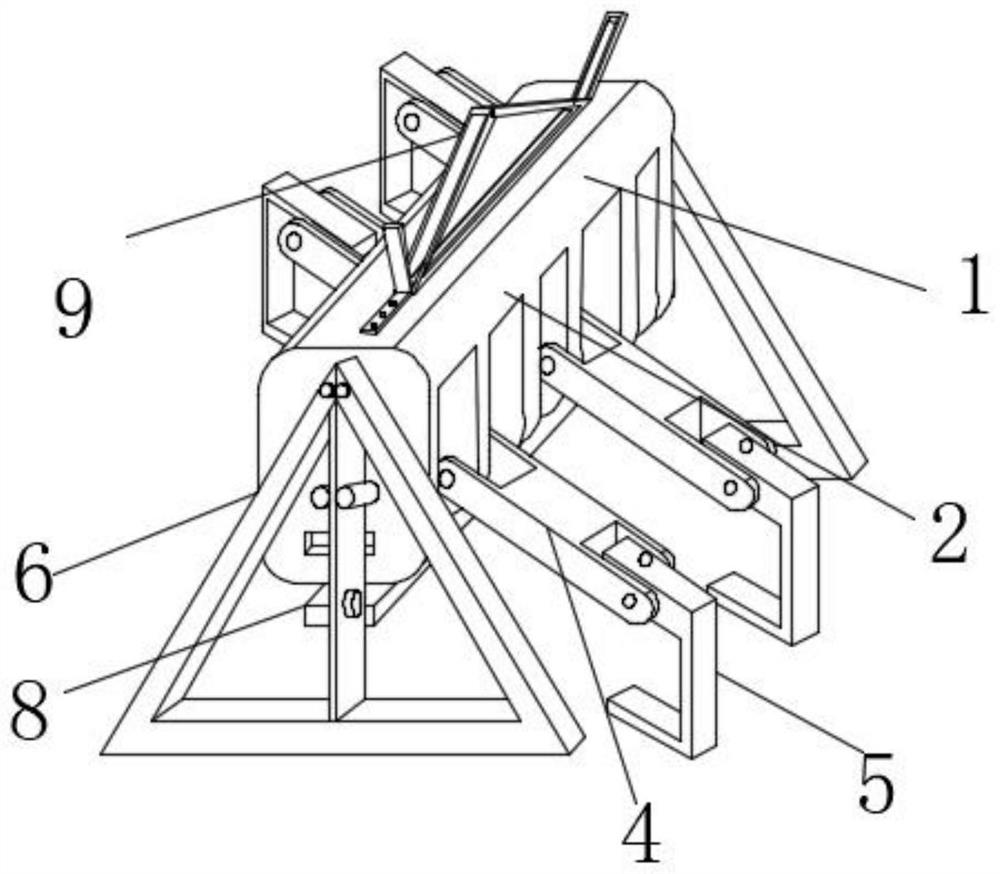
[0041] As an embodiment of the present invention, a lifting mechanism 9 is movably installed on the outer surface of the upper end of the rectangular plate 2, and the lifting mechanism 9 is composed of a triangular frame 91 and an acute-angle splint 92, and the number of the acute-angle splint 92 is two. The two acute-angle splints 92 are front-to-back symmetric, and both of them are fixedly installed on the positions of the front and rear end outer surfaces of the triangular frame 91 respectively. The front and rear end outer surfaces of frame 91 are all provided with empty groove 94, and the inside of triangular frame 91 is provided with transverse groove 95 near the position of lower end, and the inside of described acute angle splint 92 is provided with slotted hole 96 near the position of upper end, and its quantity There are several, the internal thread of the slot hole 96 is connected with a bolt, and the internal thread of the bolt passing through the slot hole 96 is co...


PUM


Abstract

The invention provides a lifting appliance for a crane. The lifting appliance comprises a clamping mechanism, the clamping mechanism is composed of a rectangular plate and a plurality of partition plates, the multiple partition plates are fixedly arranged in the rectangular plate, limiting holes I are formed in the positions, close to the lower ends of one sides, of the outer surfaces of the frontends of the multiple partition plates close to the middle, the front limiting hole I and the rear limiting hole I are opposite in position, I-shaped connecting frames are movably connected into the limiting holes I, and limiting holes II are further formed in the positions, close to the two sides, of the outer surfaces of the front ends and the rear ends of the I-shaped connecting frames. The lifting appliance has the advantages that the grabbing area is large, the grabbing force is stable, large coil steel can be conveniently lifted, the balance of a lifting appliance body is reinforced through a front baffle structure and a rear baffle structure, the phenomenon that the coil steel topples out from the front end and the rear end in the lifting process, and consequently danger is caused can be avoided, the coil steel of different layer heights can be conveniently reinforced and limited through a limiting structure, compression and storage are facilitated, a lifting mechanism can keepbalance in the lifting process, accumulation of a large amount of rainwater is prevented, rusting and corrosion are reduced, and lifting safety is guaranteed.

Description

technical field [0001] The invention relates to the technical field of crane spreaders, in particular to a crane spreader. Background technique [0002] Special slings such as hooks, wire ropes, and chains are commonly used in the spreader. Lifting suction cups, clamps and forks can be used as special spreaders on the crane for a long time, and can also be used as replaceable auxiliary spreaders hanging on the spreader. It is used temporarily on the hook, and is often used in multi-cargo warehouses and yards to improve operating efficiency. Coil steel, which is often loaded and unloaded at port terminals, is a stacked cylindrical rigid body with a weight ranging from 5 tons to 35 tons. At present, for the handling of coiled steel at low cargo levels, generally the fork knife of a forklift is inserted into a cantilevered beam, and then the beam is inserted into the coiled steel cylinder to pick up and transport. [0003] In the process of realizing the present invention, th...

Claims


Application Information

Patent Timeline
Patent Type & Authority Applications(China)
IPC IPC(8): B66C1/30B66C1/42B66C13/06
CPCB66C1/30B66C1/422B66C13/06
Inventor 朱文甫孙乐强
Owner ZHUHAI TIANLI HEAVY IND
Why Eureka
Try Eureka