Hydraulic hammer

A hydraulic hammer and hydraulic cylinder technology, applied in construction, sheet pile walls, foundation structure engineering, etc., can solve problems such as complex structure, unreliable valve action, and inability to effectively eliminate impact quality

Inactive Publication Date: 2003-10-22
"罗帕特普琉斯"有限责任公司
View PDF0 Cites 0 Cited by
  • Summary
  • Abstract
  • Description
  • Claims
  • Application Information

AI Technical Summary

Problems solved by technology

[0005] The main disadvantage of this device is: idling, that is, at the end of the upward movement of the piston and impact mass, the action of the closed valve is unreliable
[0006] Not only the relevant calculations of the working process have confirmed the above-mentioned shortcomings of this device, but also our own tests have confirmed the above-mentioned shortcomings: when we process the hammer, we first use the similar valves mentioned, be

Method used


Image

  • Hydraulic hammer
  • Hydraulic hammer
  • Hydraulic hammer

Examples


Embodiment Construction

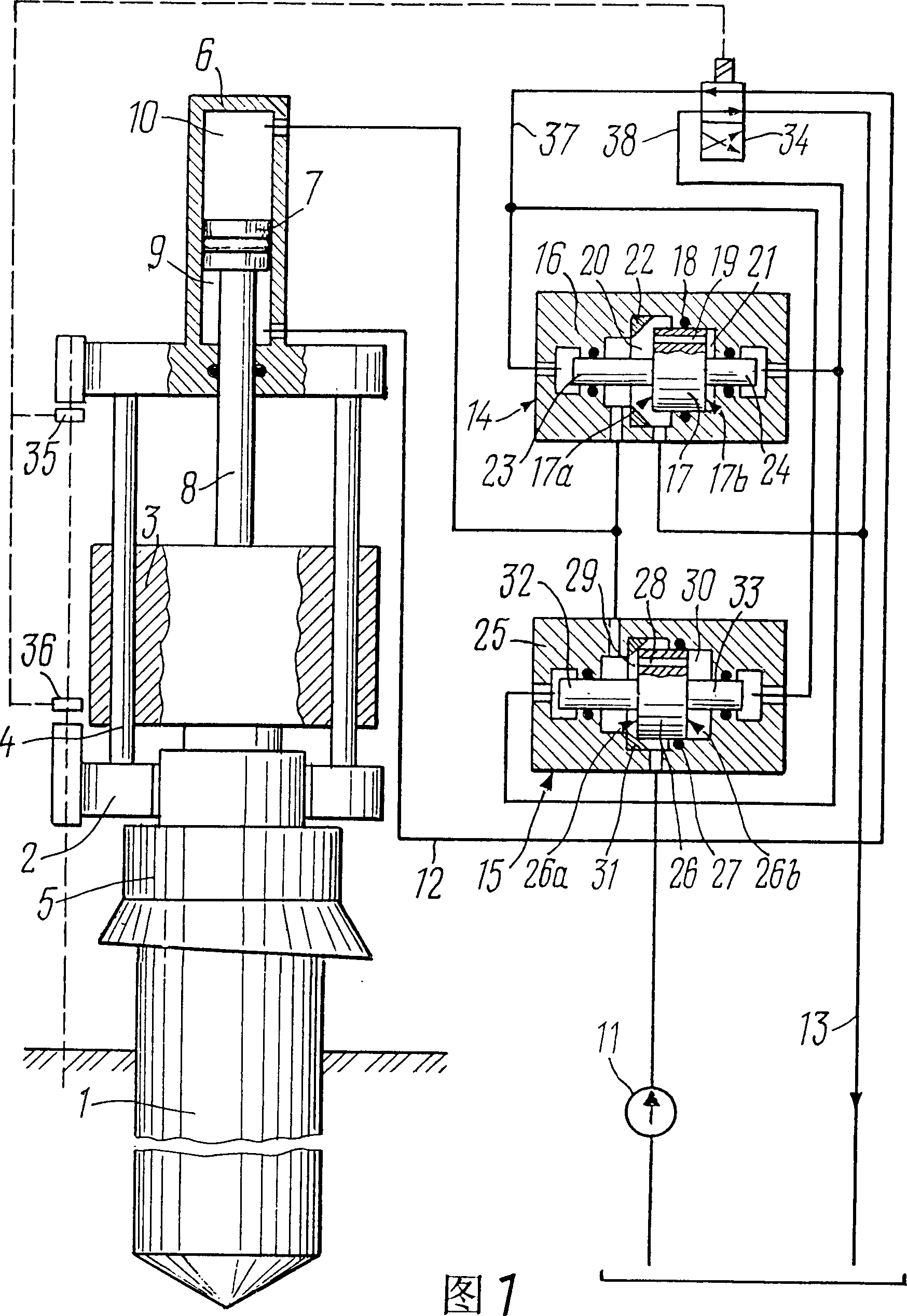
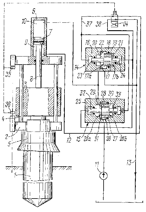
[0018] Figure 1 shows that a pile 1 is driven into the soil with a hydraulic hammer of the present invention. It includes a shell 2; an impact mass 3 that can reciprocate along the guide rod 4 of the shell 2; a pile cap 5 located between the impact mass 3 and the pile 1; a double-acting hydraulic cylinder 6 that moves the impact mass 3, which is fixed In the housing 2, there is a piston 7 with a connecting rod 8, the piston 7 forms a connecting rod cavity 9 in the direction of the pile 1 in the hydraulic cylinder 6, and a piston cavity 10 is arranged on the other side of the piston 7, and the connection The rod 8 is connected with the impact mass 3; the pump 11; the pressurizing pipe 12 and the overflow pipe 13 which are constantly connected with the connecting rod cavity 9; two double-position valves 14 and 15. The valve 14 includes a housing 16, a valve member 17, a gasket 18 of the valve member 17 in the housing 16, a channel 19 in the valve member 17, a chamber 20 in the d...


PUM


Abstract

A hydraulic hammer, comprising a housing (2); an impact mass (3) equipped with a guide rod (4) reciprocatingly moving; a hydraulic cylinder (6) for moving the impact mass (3), which is fixed on the housing ( In 2), the piston (7) with the connecting rod (8) forms a connecting rod cavity (9) in the direction of the pile (1) in the hydraulic cylinder (6), and the other side forms a piston cavity (10). The connecting rod (8) is connected with the impact mass (3), the pump (11) with the overflow pipe (13) and the pressurizing pipe (12) which is connected with the connecting rod cavity ( 9) are connected, and also include two double-position valves (14, 15), which are used to connect with the piston chamber (10) of the hydraulic hammer (6) through the pressurizing pipe (12) or overflow pipe (13); each Valve parts (17, 26) are made into an oil cylinder form, arranged and sealed in the housing of the valve, and its outer diameter is close to the diameter of the contact surface of the valve. Wherein the chamber at the front end of the valve part communicates with the chamber at the rear end of the valve part facing the valve seat.

Description

technical field [0001] This invention relates to construction machinery for driving piles, sheet piles, pipes and other construction components into soil. Background technique [0002] ΦPΓ N2900221 in the patent, discloses a kind of hydraulic device for piling in EO2D7 / 10. It consists of a housing; an impact mass connected to the housing; a hydraulic cylinder with a power piston whose connecting rod is connected to the impact mass; a hydraulic distributor arranged in the hydraulic cylinder and having a slider, which includes a plunger oil valve , this valve interacts with the face of the power piston. The plunger oil valve forms a closed container (control cylinder) connected to an accumulator in which a piston is arranged, the stroke of which is limited by a brake. The control cylinder is connected with the drainage equipment through the safety valve. [0003] This device has a strong working capacity and has been implemented in practice, but it has two disadvantages, na...

Claims


Application Information

Patent Timeline
IPC IPC(8): E02D7/10
CPCE02D7/10
Inventor 维克托·亚历山德罗维奇·库夫申诺夫
Owner "罗帕特普琉斯"有限责任公司
Why Eureka
Try Eureka