
Valve assembly and scroll compressor comprising same

A scroll compressor and valve assembly technology, applied in the field of compressors, can solve problems such as poor reliability and complex capacity adjustment structure

Pending Publication Date: 2021-03-19
ZHUHAI GREE REFRIGERATION TECH CENT OF ENERGY SAVING & ENVIRONMENTAL PROTECTION
View PDF2 Cites 0 Cited by
  • Summary
  • Abstract
  • Description
  • Claims
  • Application Information

AI Technical Summary

Problems solved by technology

[0005] The purpose of the present invention is to provide a valve assembly and a scroll compressor including the valve assembly, so as to solve the technical problems of complicated structure and poor reliability of the scroll compressor capacity adjustment existing in the prior art

Method used


Image

  • Valve assembly and scroll compressor comprising same
  • Valve assembly and scroll compressor comprising same
  • Valve assembly and scroll compressor comprising same

Examples


Embodiment 1

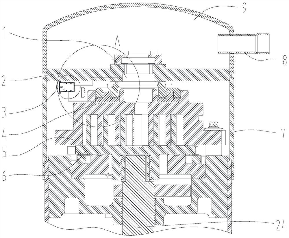
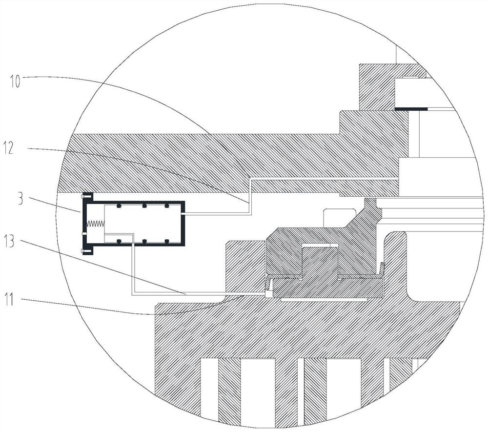
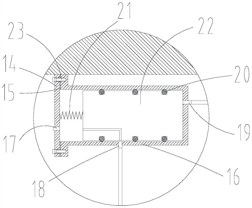
[0051] like figure 1 As shown, the present invention provides a scroll compressor. The scroll compressor is mainly composed of a partition plate 2, a static disk 5, a moving disk 6, a housing 7, an exhaust pipe 8, and a crankshaft 24. There is an exhaust chamber 9 between the plate 2 and the housing 7 , the exhaust port 1 of the static disc communicates with the exhaust chamber 9 , and the exhaust pipe 8 is installed on the housing 7 and communicates with the exhaust chamber 9 . The crankshaft 24 is connected to the moving disk 6 through transmission, which can drive the rotating disk 6 to rotate; between the static disk 5 and the housing 7 is an air suction chamber 25; Rotating and translating to form a series of crescent-shaped compression chambers 4 between the two to realize the compression process of the gaseous refrigerant.

[0052] It also includes a valve assembly 3 arranged in the scroll compressor, such as Figure 1-Figure 3 As shown, the valve assembly 3 is assemb...

Embodiment 2

[0057] like Figure 13 As shown, in this embodiment, only the differences from Embodiment 1 are described, and the difference between Embodiment 2 and Embodiment 1 is that the introduction end of the exhaust channel 10 is not the exhaust port 1 of the static disk, but the exhaust Cavity 9. In this embodiment, the exhaust channel 10 is arranged vertically through the partition plate 2 , the top end communicates with the exhaust chamber 9 , and the lower end connects with the exhaust hose 12 . In the second embodiment, the exhaust refrigerant in the exhaust chamber 9 is led to the pressure discharge chamber of the valve assembly 3, and the drive for changing the position of the valve core is realized under partial load.

[0058] It should first be explained here that "inward" refers to a direction toward the center of the accommodating space, and "outward" refers to a direction away from the center of the accommodating space.


PUM


Abstract

The invention provides a valve assembly and a scroll compressor comprising the same, relates to the technical field of compressors, and solves the technical problems of complex capacity adjusting structure and poor reliability of the scroll compressor. The valve assembly comprises a valve body, the valve body is provided with an exhaust flow path, a suction flow path and a medium-pressure flow path which communicate with an exhaust section, a suction section and a compression section of the scroll compressor respectively, and a capacity adjusting piece capable of achieving state switching through suction and exhaust pressure is arranged in the valve body. When the capacity adjusting piece is in different states, the suction flow path and the medium-pressure flow path are in a connected ordisconnected state, so that capacity adjustment of the scroll compressor during partial-load operation or full-load operation is achieved. The scroll compressor comprises the valve assembly. Accordingto the scroll compressor, communication of different pressure areas is achieved through the movement of a suction and exhaust pressure control valve element, capacity adjustment during full-load operation and partial-load operation of the scroll compressor is achieved, the complexity degree of a compressor structure is reduced, and the operation reliability of the compressor is improved.

Description

technical field [0001] The invention relates to the technical field of compressors, in particular to a valve assembly and a scroll compressor comprising it. Background technique [0002] For the scroll compressor, at the beginning of its design, the capacity will be formulated according to the maximum load that exists during its operation. However, during the operation process, the required capacity of the compressor cannot reach the maximum value at some time, but the compressor still operates at the maximum capacity, which will affect the overall performance of the system and cause unnecessary waste of energy. [0003] To solve this problem, traditionally, a mechanical structure is usually installed inside the compressor, such as the scroll compressors disclosed in Chinese patents CN105026764B and CN106032799B. The contact and separation of the dynamic and static disks are controlled by solenoid valves, so as to realize capacity adjustment. This kind of control method of ...

Claims


Application Information

Patent Timeline
IPC IPC(8): F16K11/07F04C28/26
CPCF04C28/26F16K11/0712F16K11/0716
Inventor 徐嘉单彩侠李立民郭求和
Owner ZHUHAI GREE REFRIGERATION TECH CENT OF ENERGY SAVING & ENVIRONMENTAL PROTECTION
Learn More