A radiant tube burner that can roll smoke to achieve flameless combustion

A radiant tube and burner technology, applied in the field of radiant tube burners, can solve the problems of limited and unreachable maximum flue gas return flow, and reduced air supply to the radiant tube, so as to avoid long-term shutdowns, save use costs, and avoid Fragile effect

Active Publication Date: 2022-07-15
WUHAN UNIV OF SCI & TECH
View PDF15 Cites 0 Cited by
  • Summary
  • Abstract
  • Description
  • Claims
  • Application Information

AI Technical Summary

Problems solved by technology

Although this structure can play a role in adjusting the flue gas return flow, the maximum flue gas return flow provided by the return flow structure itself is quite limited, and it cannot achieve flameless combustion.
[0006] At the same time, the above-mentioned radiant tube burner and radiant tube combustion system, because the designed smoke entrainment port is placed at the intersection of the end of the air pipe and the connecting pipe, and is opposite to the position of the smoke outlet, the smoke is subjected to the negative pressure of the smoke exhaust. The common pulling effect with the negative pressure of the entrainment can easily cause the following disadvantages: First, for the radiant tube using the pumping type, the combustion-supporting air is blown in by the blower, and the smoke is exhausted by the smoke exhaust fan. The negative pressure caused by the smoke exhaust fan is generally If it is greater than 400Pa, when the speed of the air ejected from the tapered nozzle reaches 100m / s, the negative pressure in the entrainment area is about 200Pa. At this time, the negative pressure of the smoke exhaust is much greater than the pressure drop in the entrainment area, and the smoke flows more towards the smoke exhaust Therefore, the entrainment volume cannot meet the design requirements, or the tapered nozzle needs to provide a huge ejection speed, and the current on-site blower cannot meet this requirement
Second, the performance of the fan on the production site fluctuates. If the exhaust pipe is blocked, the air pipe and the exhaust pipe are damaged, etc., there will be safety hazards such as a sharp decline in the performance of the fan.
When the blowing pressure of the air pipe is not enough, the speed of the tapered nozzle decreases, the resulting pressure difference decreases, and the original entrainment volume cannot be maintained. At this time, a large amount of smoke and even air will be drawn by the huge pressure of the exhaust fan, causing the radiant tube The air supply is reduced, oxygen-poor combustion is carried out in the radiant tube, the performance of the radiant tube is reduced, and a large amount of toxic gases such as CO are generated

Method used


Image

  • A radiant tube burner that can roll smoke to achieve flameless combustion
  • A radiant tube burner that can roll smoke to achieve flameless combustion
  • A radiant tube burner that can roll smoke to achieve flameless combustion

Examples


Embodiment 1

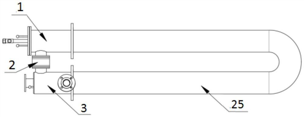
[0035] Embodiment 1: The present invention provides a radiant tube burner that can roll smoke to achieve flameless combustion. The structure of the burner when used together with the radiant tube is as follows: figure 1 As shown, the burner 1 is installed at the inlet end of the radiant tube 25, and the heat exchanger 3 is installed at the outlet end of the radiant tube.

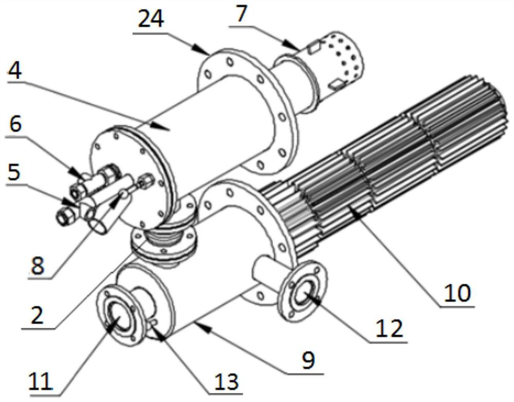
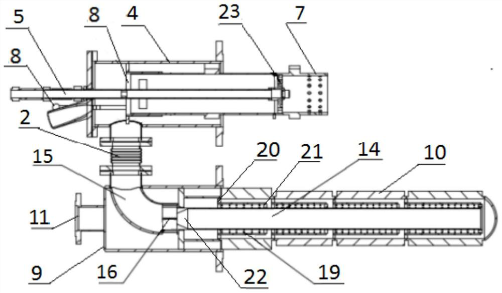
[0036] For the external overall structure and internal structure of the radiant tube burner of the present invention, please refer to figure 2 , 3 , the burner is provided with a burner 1, a mixer 2 with an expansion joint returning flue gas and combustion-supporting air, and a heat exchanger 3, the burner is provided with a burner shell 4, and the gas enters the burner shell through a gas pipe 5, The end of the gas pipe is provided with an air distribution plate 23 and a gas nozzle; the burner is connected to the radiant pipe 25 through a connecting flange 24 .

[0037] One end of the burner shell is ins...

Embodiment 2

[0043] Embodiment 2: The present invention provides a radiant tube burner that can roll smoke to achieve flameless combustion. Its structure and working process are basically the same as those of Embodiment 1, and the difference is that the smoke return pipe 16 is sleeved. Sleeve 18, one end of the handle of the return window adjustment rod 13 is exposed outside the heat exchanger shell 9, and the other end of the return window adjustment rod is connected to the sleeve 18, see the sleeve structure Figure 8 , 9, the sleeve is a cylindrical structure, the right end of the sleeve is provided with a closed ring 181, the closed ring is provided with a channel, the sleeve and the flue gas return pipe are installed concentrically, when the handle of the return window adjustment rod 13 is pushed into the heat exchanger shell, The sleeve can be gradually opened until the return window is fully opened. When the handle is gradually pulled out of the heat exchanger shell, the sleeve can ...


PUM


Abstract

The invention relates to a radiant tube burner capable of cigarette smoke to realize flameless combustion. The burner provided with a burner and a heat exchanger are respectively installed at both ends of the radiant tube; Used to adjust the ratio of primary and secondary air entering the burner; the burner shell is connected to the jet port of the mixer, the other end of the mixer is connected to the heat exchanger, and the combustion air and the return flue gas are mixed in the mixer; Equipped with an air pipe, the straight pipe in the air pipe is connected to the curved pipe through the flue gas return pipe. There is a tapered pipe in the straight pipe. The wall of the flue gas return pipe is evenly distributed with return windows. Sleeve; the opening of the return window can be adjusted by rotating the curtain or the movement of the sleeve, which is used to adjust the entrainment amount of the flue gas; the burner has the advantages of low cost of use, long life, easy promotion, and good effect of energy saving, emission reduction and noise reduction, etc. The characteristic is that the maximum smoke entrainment amount is 55%, Kv=1, and the flameless (MILD) combustion of the burner can be realized.

Description

technical field [0001] The present invention relates to a burner, in particular to a radiant tube burner that can roll smoke to achieve flameless combustion. Background technique [0002] With the continuous progress of science and technology, modern iron and steel enterprises have increasingly higher requirements for product heating quality, especially in order to effectively avoid oxidation and decarburization of the heated surface, indirect heating technology has become more and more widely used. Radiant tube is an important heating device to realize indirect heating function. In order to improve the thermal efficiency of radiant tube, heat exchangers have been widely used in radiant tube burners. Two-stage and even multi-stage heat exchangers have been developed and applied. Radiant tube staged combustion technology can improve The surface temperature of the radiant tube is uniform, and the NOx emission level can be reduced to a certain extent. However, there are still ...

Claims


Application Information

Patent Timeline
Patent Type & Authority Patents(China)
IPC IPC(8): F23D14/02F23D14/64F23D14/46F23D14/60
CPCF23D14/02F23D14/64F23D14/46F23D14/60
Inventor 潘妮徐家强贺铸许学成谭方关
Owner WUHAN UNIV OF SCI & TECH
Why Eureka
Try Eureka