Film tension detection device and operation method thereof

A technology of tension detection and thin film, which is applied in the direction of measuring devices, using stable tension/pressure to test the strength of materials, instruments, etc., can solve the problems of poor stability, low efficiency, and high labor intensity, so as to improve the clamping effect and improve The effect of detection efficiency and labor intensity reduction

Inactive Publication Date: 2021-03-19
孔江君
View PDF0 Cites 1 Cited by
  • Summary
  • Abstract
  • Description
  • Claims
  • Application Information

AI Technical Summary

Problems solved by technology

[0004] The purpose of the present invention is to solve the problem of low efficiency and high labor intensity and poor stability in the detection process of manual tension detection in the prior art, and proposes a film tension detection device

Method used


Image

  • Film tension detection device and operation method thereof
  • Film tension detection device and operation method thereof
  • Film tension detection device and operation method thereof

Examples


Embodiment 1

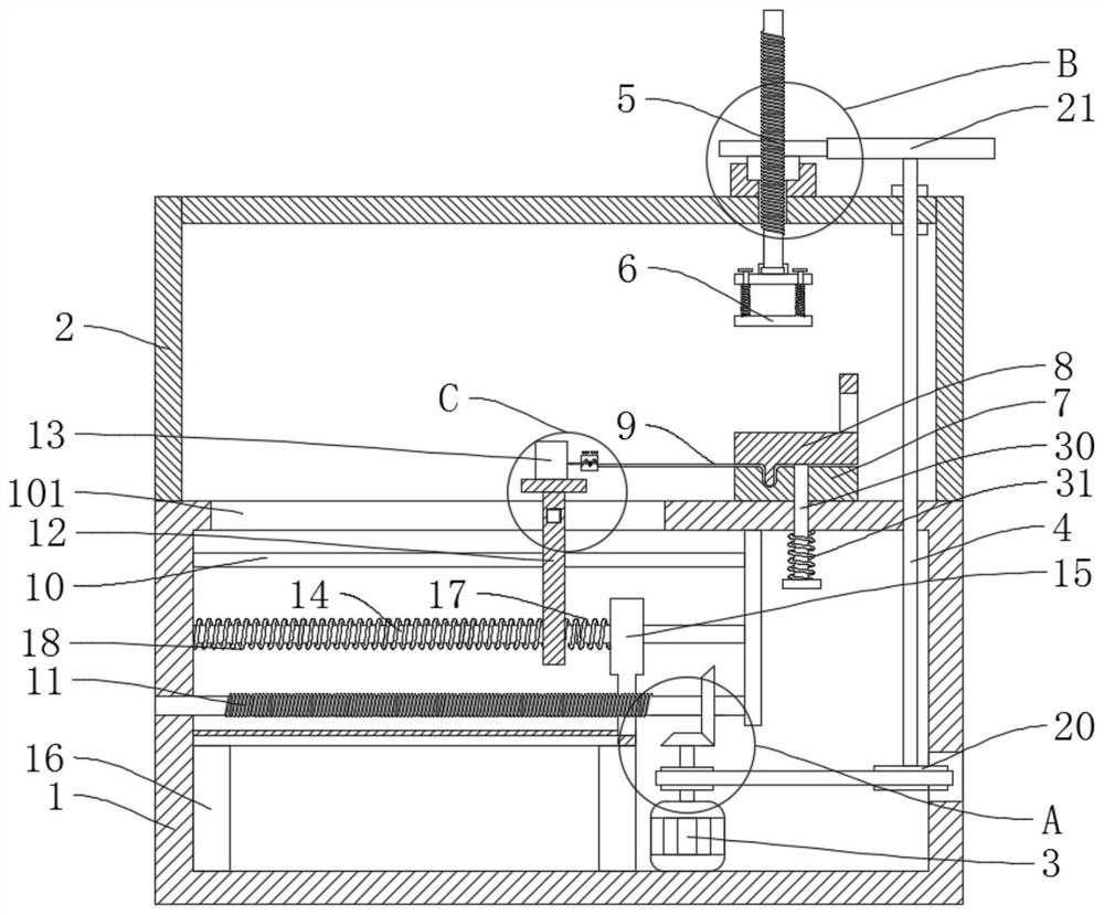
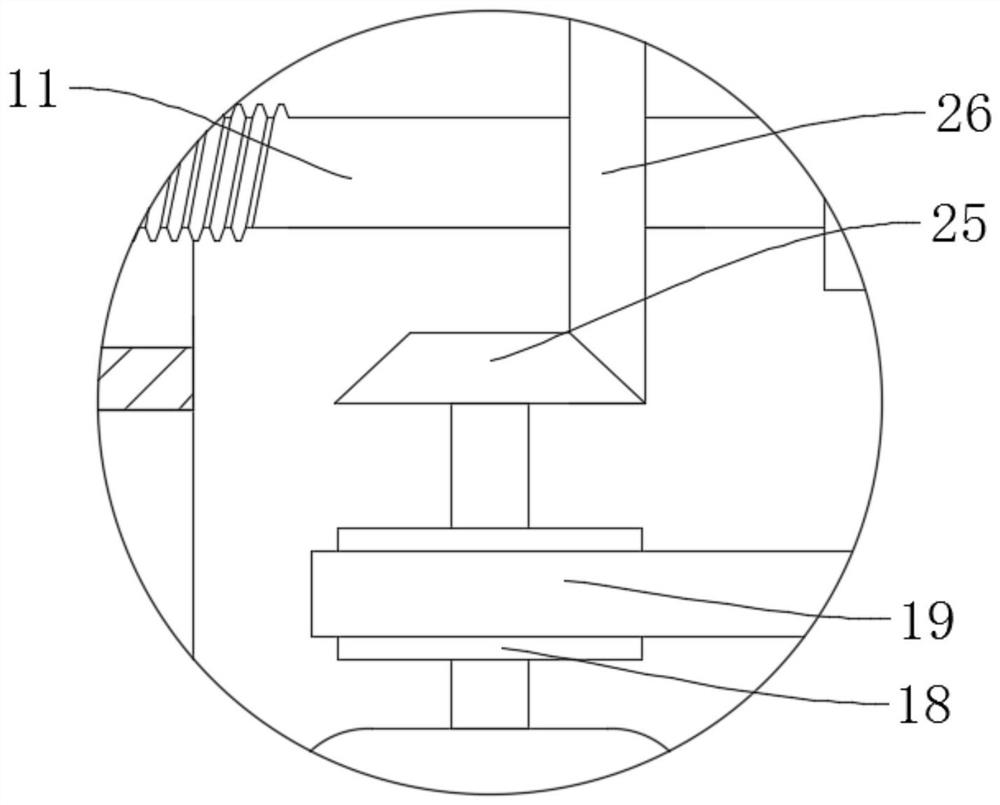
[0036] refer to figure 1 , image 3 , Figure 4 , Figure 5 , Figure 6 , Figure 7, a film tension detection device, comprising a base 1, a film to be detected 9 and a tension detector 13, a drive mechanism is fixedly connected to the base 1, a connecting rod 4 and a second threaded rod 11 are connected in rotation in the base 1, and the connecting rod 4 and the second threaded rod 11 are connected with the drive mechanism in rotation, the connecting rod 4 is connected with the first threaded rod 5 in rotation, the first threaded rod 5 is fixedly connected with the pressing plate 6, and the second threaded rod 11 is slidably connected with the slide plate 12. The slide plate 12 is fixedly connected with a support base 121, the tensile tester 13 is fixedly connected with the support base 121, the base 1 is fixedly connected with a workbench 7, the workbench 7 is provided with a clamping plate 8, and the detected film 9 is fixed Connected between the workbench 7 and the cl...

Embodiment 2

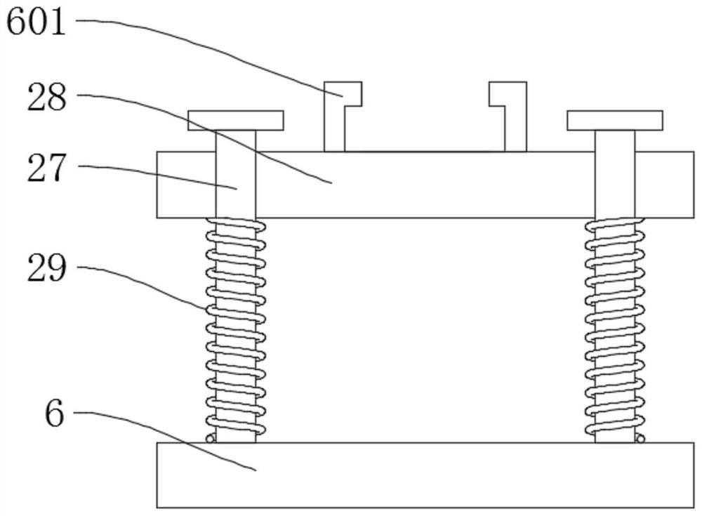
[0047] refer to figure 1 , figure 2 , Figure 5 , a film tension detection device, comprising a base 1, a film to be detected 9 and a tension detector 13, a drive mechanism is fixedly connected to the base 1, a connecting rod 4 and a second threaded rod 11 are connected in rotation in the base 1, and the connecting rod 4 and the second threaded rod 11 are connected with the drive mechanism in rotation, the connecting rod 4 is connected with the first threaded rod 5 in rotation, the first threaded rod 5 is fixedly connected with the pressing plate 6, and the second threaded rod 11 is slidably connected with the slide plate 12. The slide plate 12 is fixedly connected with a support base 121, the tensile tester 13 is fixedly connected with the support base 121, the base 1 is fixedly connected with a workbench 7, the workbench 7 is provided with a clamping plate 8, and the detected film 9 is fixed Connected between the workbench 7 and the clamping plate 8, the tensile tester 13...

Embodiment 3

[0058] An operation method of a film tension detection device adopts the following steps:

[0059] S1, pull the handle on the clamping plate 8, place the tested film 9 on the workbench 7, release the handle, and initially clamp the tested film 9 by the tension of the fourth spring 31 on the third slide bar 30, The U-shaped block 801 on the clamping plate 8 is engaged with the U-shaped groove 701 to further improve the clamping effect;

[0060] S2, the other end of the tested film 9 is fixed on the fixed block 131 on the tensile tester 13 to complete the fixation;

[0061] S3, start the motor 3, and the motor 3 drives the first threaded rod 5 to descend, and the pressing plate 6 is offset against the clamping plate 8 to further improve the clamping effect and prevent the detected film 9 from falling off during the detection process;


PUM


Abstract

The invention discloses a film tension detection device and an operation method thereof, and belongs to the field of tension detection. The film tension detection device comprises a base, a to-be-detected film and a tension detector; a driving mechanism is fixedly connected to the base; a connecting rod and a second threaded rod are rotatably connected into the base; the connecting rod and the second threaded rod are both rotatably connected with the driving mechanism; a first threaded rod is rotatably connected to the connecting rod; a pressing plate is fixedly connected to the first threadedrod; a sliding plate is slidably connected to the second threaded rod; the tension detector is fixedly connected to a supporting base; a workbench is fixedly connected to the base; and a clamping plate is arranged on the workbench. The clamping effect of the to-be-detected film is strengthened, so that the fixing effect and stability of tension detection of the film are improved, meanwhile, the working efficiency of manual tension detection is improved, and the pulling strength of operators is reduced.

Description

technical field [0001] The invention relates to the technical field of tension detection, in particular to a film tension detection device and an operation method thereof. Background technique [0002] A film is a thin, flexible, transparent sheet; made of plastic, adhesive, rubber, or other material. Thin film is scientifically explained as: a 2-dimensional material formed by depositing atoms, molecules or ions on the surface of a substrate. Example: optical film, composite film, superconducting film, polyester film, nylon film, plastic film, etc.; films are widely used in electronics, machinery, printing and other industries. There is no unified regulation on the classification of films. Usually people are accustomed to the following three classification methods: according to the raw materials used for film forming: polyethylene film, polypropylene film, polyvinyl chloride film and polyester film, etc., according to the film use: agricultural film (here based on agricult...

Claims


Application Information

Patent Timeline
IPC IPC(8): G01N3/08G01N3/04
CPCG01N3/04G01N3/08G01N2203/0017G01N2203/005G01N2203/0282G01N2203/0676
Inventor 孔江君
Owner 孔江君
Why Eureka
Try Eureka