Redundancy switching device and control method thereof

A technology of redundant switching and main control, which is applied in general control systems, control/regulation systems, instruments, etc., can solve the problems of no automatic switching devices, etc., and achieve the effect of ensuring normal operation

Pending Publication Date: 2021-03-19
CHONGQING HONGJIANG MACHINERY
View PDF5 Cites 1 Cited by
  • Summary
  • Abstract
  • Description
  • Claims
  • Application Information

AI Technical Summary

Problems solved by technology

At present, the redundant switching of the electronic control system adopts manual switching, and there is no automatic switching device

Method used


Image

  • Redundancy switching device and control method thereof
  • Redundancy switching device and control method thereof
  • Redundancy switching device and control method thereof

Examples


Embodiment Construction

[0046] The present invention will be further described below in conjunction with the accompanying drawings.

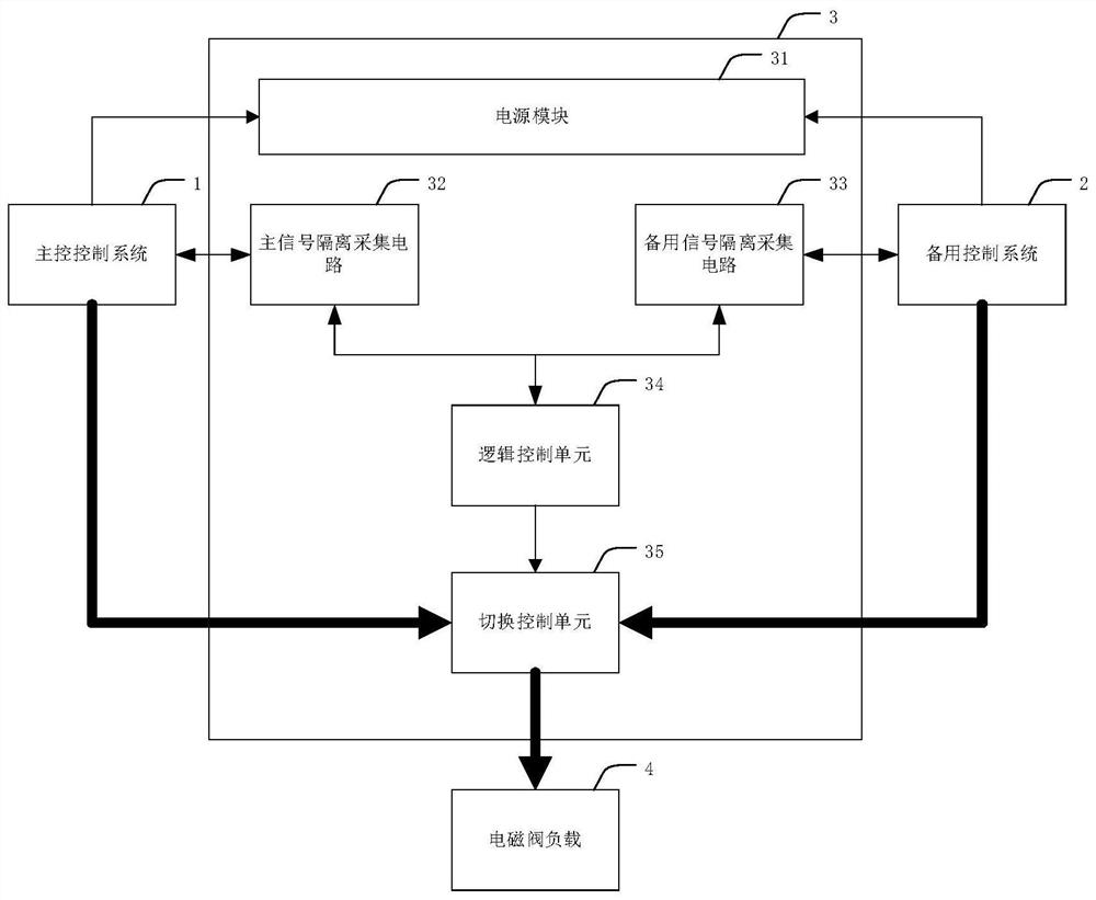
[0047] A redundant switching device disclosed in the present invention includes a main control system 1 , a backup control system 2 , a power supply module 31 and a load redundant switching device 3 .

[0048] The load redundancy switching device 3 includes a main signal isolation acquisition circuit 32 , a standby signal isolation acquisition circuit 33 , a logic control unit 34 , a switching control unit 35 and a load.

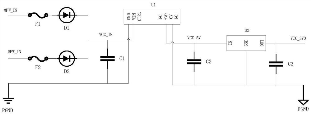
[0049] The power module 31 accepts the power supply voltage input from the main control system 1 or the standby control system 2 , and outputs the power supply voltage to the logic control unit 34 and the switching control unit 35 .

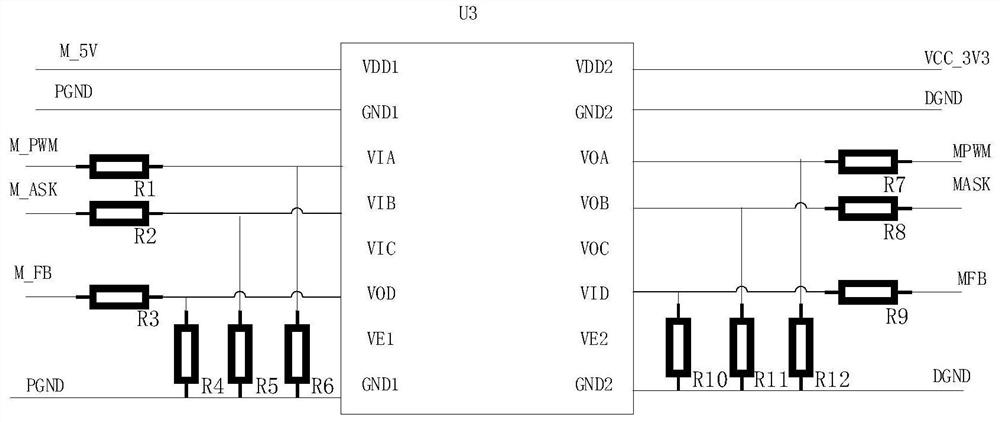
[0050]When the main control system 1 is working normally, it normally outputs the main control heartbeat command M_PWM; the main control system 1 also outputs the main control request command M_ASK, which can be set to ...


PUM


Abstract

The invention discloses a redundancy switching device and a control method thereof, which are mainly suitable for automatic switching control of a control system on load control of a marine diesel engine in a dual-control system mode. And the redundancy switching device receives a heartbeat control instruction and a control request instruction of the control system, carries out judgment accordingto an instruction signal of the control system, finally determines the ownership of the control right of the load, and switches the load to the control system with the control right for control through the switching of a switching control unit.

Description

technical field [0001] The invention relates to automatic switching control of loads such as fuel injectors and unit pumps of a marine diesel engine under a dual-ECU control mode, and in particular relates to a redundant switching device and a control method thereof. Background technique [0002] With the development of marine electronic technology, especially in the marine power system, the requirements for the safety of the electronic control system are getting higher and higher. In order to avoid the shutdown of the diesel engine due to partial failure of the electronic control system in the power system of the diesel engine, redundancy requirements are put forward for the electronic control system of the diesel engine. At present, the redundant switching of the electronic control system adopts manual switching, and there is no automatic switching device for the time being. Therefore, it is necessary to develop a device that can automatically switch the load from the mai...

Claims


Application Information

Patent Timeline
IPC IPC(8): G05B9/03
CPCG05B9/03
Inventor 桑印李鹏豪汤自强王文成卢训张明刚贾波凯杨雪莲
Owner CHONGQING HONGJIANG MACHINERY
Why Eureka
Try Eureka