An iron core winding device for transformer production and processing

A winding device, transformer technology, applied in the direction of inductance/transformer/magnet manufacturing, coil manufacturing, electrical components, etc., can solve the problems of low work efficiency, time-consuming, poor work quality, etc., and achieve the effect of saving manpower

Active Publication Date: 2022-05-10
赣州和信诚电子有限公司
View PDF24 Cites 0 Cited by
  • Summary
  • Abstract
  • Description
  • Claims
  • Application Information

AI Technical Summary

Problems solved by technology

[0005] In order to overcome the shortcomings of manual winding, which takes a lot of time, low work efficiency, and poor work quality, the technical problem of the present invention is to provide a transformer capable of automatic winding, high work efficiency, and good work quality. Iron core winding device

Method used


Image

  • An iron core winding device for transformer production and processing
  • An iron core winding device for transformer production and processing
  • An iron core winding device for transformer production and processing

Examples


Embodiment 1

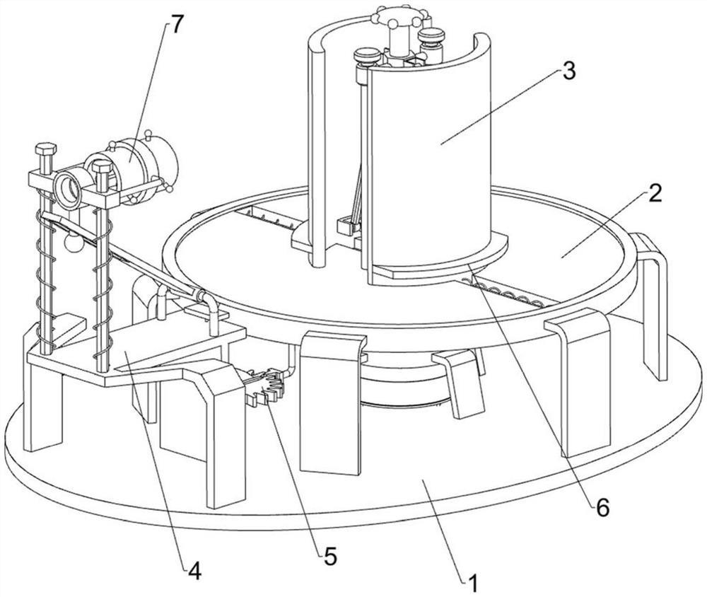
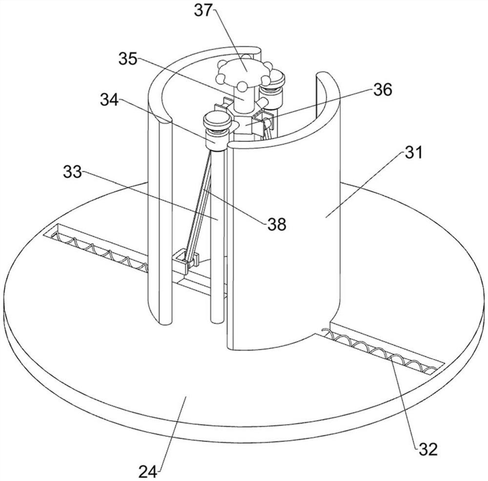
[0023] An iron core winding device for transformer production and processing, such as Figure 1-6 As shown, it includes a base 1 , a rotating assembly 2 and a fixed assembly 3 , the base 1 is provided with a rotating assembly 2 which rotates by rotation, and the rotating assembly 2 is provided with a fixed assembly 3 which is fixed by sliding.

[0024] When using the device, the staff puts the iron core on the fixed assembly 3, and after putting it away, winds one end of the copper wire around the iron core, and then, the staff starts the rotating assembly 2, and drives the fixed assembly 3 through the rotating assembly 2 Turn to wind the copper wire on the iron core. After the winding is completed, the staff closes the rotating assembly 2.

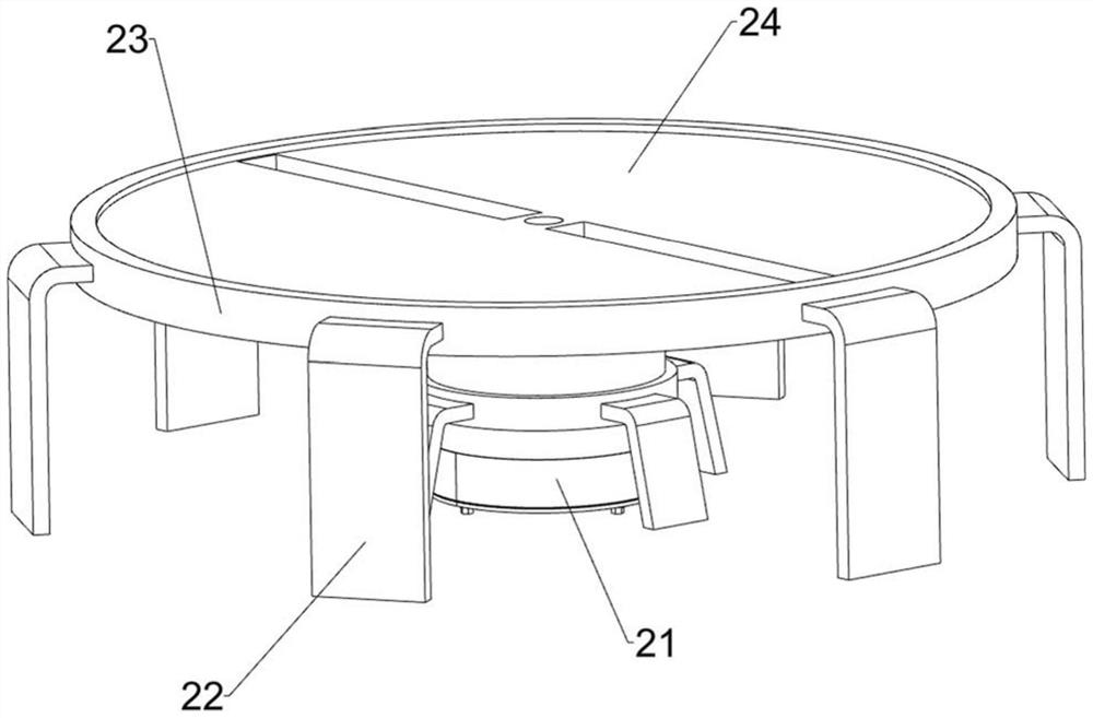
[0025] Such as figure 1 , figure 2 , image 3 with Figure 5 As shown, the rotating assembly 2 includes a geared motor 21, a mounting block 22, an annular guide rail 23 and a turntable 24, the base 1 is fixedly connected with a geare...

Embodiment 2

[0030] On the basis of Example 1, such as figure 1 , Figure 4 with Figure 5 As shown, a lead assembly 4 is also included, and the lead assembly 4 includes a special-shaped frame 41, a prismatic guide rod 42, a second spring 43, a first slider 44 and a wire ring 45, and the left part of the base 1 is provided with a special-shaped frame 41, The left part of the special-shaped frame 41 is provided with two prismatic guide rods 42, and the first slide block 44 is all slidably provided on the prismatic guide rod 42, and the first slide block 44 and the prismatic guide rod 42 are all wound with the first slide block. Two springs 43 , and a wire loop 45 is arranged between the two first sliders 44 .

[0031] When winding the iron core, the worker passes one end of the copper wire through the wire ring 45 and winds it on the iron core. While winding, the worker pushes the first slider 44 to slide on the prismatic guide rod 42, The second spring 43 is compressed and reset thereup...


PUM


Abstract

The invention relates to an iron core winding device, in particular to an iron core winding device for transformer production and processing. Provided is an iron core winding device capable of automatic winding, high working efficiency and good working quality for transformer production and processing. An iron core winding device for transformer production and processing, comprising: a base; a rotating component installed on the base and rotated by rotating; a fixed component installed on the rotating component and fixed by sliding. The invention can provide power when the iron core is wound through the rotating component, fix the iron core through the fixed component, and wind the iron core, and can drive the copper wire to move up and down during the winding through the wire component, so that the copper wire can be wound It is more uniform, and the swing component can no longer need to manually push the first slider, which saves a lot of manpower, and the support plate can support the iron core during winding, which is more convenient for people to use.

Description

technical field [0001] The invention relates to an iron core winding device, in particular to an iron core winding device for transformer production and processing. Background technique [0002] Transformer is a device that uses the principle of electromagnetic induction to change AC voltage. The main components are primary coil, secondary coil and iron core. The main functions are: voltage conversion, current conversion, impedance conversion, isolation, voltage stabilization, etc. [0003] In the process of transformer production, copper wire needs to be wound on the magnetic core. At present, the copper wire is generally wound on the magnetic core manually. This manual winding method takes a lot of time and has low work efficiency. , and the winding may be uneven through manual winding, and the work quality is poor, which will affect subsequent use. [0004] Therefore, it is necessary to invent a kind of iron core winding device that can automatically carry out winding, ...

Claims


Application Information

Patent Timeline
Patent Type & Authority Patents(China)
IPC IPC(8): H01F41/06H01F41/082
CPCH01F41/06H01F41/082
Inventor 王晓华
Owner 赣州和信诚电子有限公司
Why Eureka
Try Eureka