Novel electric control grounding wire clamp

A grounding clip, electric control technology, applied in conductive connection, electrical component connection, circuit and other directions, can solve problems such as inconvenient operation, loose rod head, damage to insulating gloves, etc., to achieve simple and clear use and operation, quantitative use effect, The effect of improving construction efficiency

Pending Publication Date: 2021-03-19
GUIZHOU POWER GRID CO LTD
View PDF7 Cites 1 Cited by
  • Summary
  • Abstract
  • Description
  • Claims
  • Application Information

AI Technical Summary

Problems solved by technology

Or when the hanging point of the grounding wire is not directly above the construction worker's head, due to the limited construction space of the pole tower, the direction of twisting the insulating rod will form a certain angle with the construction worker's arm, and the three-phase grounding wire clip and the wire will be It will be in the corner angle and the torque will be stressed. When the operator wears insulating gloves and twists the insulating rod, it is inconvenient to operate and may easily cause damage to the insulating gloves.
It is difficult for operators to quickly hang up the grounding wire, or even break the grounding wire, which greatly prolongs the time for hanging the grounding wire, which affects the efficiency of construction and emergency repairs
[0005] 3. Due to the limitation of the construction space of the pole tower, the twisting of the insulating pole is in most cases under the force of the torque at the angle, which often leads to the loosening of the pole head and even the breakage of the pole.

Method used


Image

  • Novel electric control grounding wire clamp
  • Novel electric control grounding wire clamp
  • Novel electric control grounding wire clamp

Examples


Embodiment 1

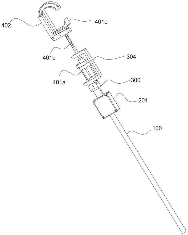
[0037] refer to figure 1 , which is the first embodiment of the present invention, provides a new type of electric control grounding clamp, which includes an insulating rod 100, a power assembly 200, a rotating assembly 300 and a clamping assembly 400, wherein the insulating rod 100; the power assembly 200, arranged on the insulating rod 100, including the installation box 201, the lithium battery 202 arranged inside the installation box 201, the Bluetooth receiver 203 arranged in the installation box 201; the rotating assembly 300, including the rotating shaft connected with the insulating rod 100 The cover 301, the rotor 302 connected to the rotating shaft cover 301, the housing 303 sleeved with the rotor 302 and the rotating rod 304 connected with the housing 303; The buckle 402 to which the telescopic piece 401 is connected.

[0038] Wherein, the insulating rod 100 forms the main rod of the grounding wire clamp for gripping, the power assembly 200 provides a power source ...

Embodiment 2

[0041] refer to figure 2 , 3 , 4, 5 are the second embodiment of the present invention, which is different from the first embodiment in that: the insulating rod 100 is made of insulating material, and one end near the power assembly 200 is provided with a U type opening, and a through hole 201 is opened on the U-shaped plate.

[0042] The installation box 201 is fixed on the U-shaped end of the insulating rod 100, and its side panels are detachable. The rotating shaft cover 301 is fixedly connected with the rotor 302 , and its radial diameter is larger than the radial diameter of the through hole 201 .

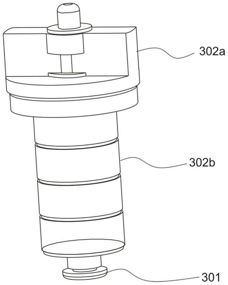
[0043]The top of the rotor 302 is provided with a rotating head 302a, and the rod is rotationally connected with the rotating head 302a, the rotating head 302a is fixedly connected with the rotating shaft cover 301, and a plurality of contact pieces 302b are wrapped on the rod.

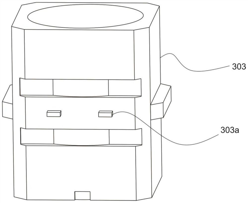
[0044] The inside of the casing 303 is provided with a groove matching the rotor 302, and a pl...


PUM


Abstract

The invention discloses a novel electric control grounding wire clamp, and the wire clamp comprises an insulating rod, a power assembly, a rotating assembly and a clamping assembly, wherein the powerassembly is arranged on the insulating rod and comprises a mounting box, a lithium battery arranged in the mounting box and a Bluetooth receiver arranged in the mounting box; the rotating assembly comprises a rotating shaft cover rotationally connected with the insulating rod, a rotor connected with the rotating shaft cover, a shell connected with the rotor in a sleeving manner and a rotating rodconnected with the shell; the clamping assembly comprises a telescopic piece arranged on the rotating rod and a buckle connected with the telescopic piece. According to the invention, the electric control grounding wire clamp can adapt to the angle formed by the working face and the insulating rod twisting shaft, rapid repair is achieved through remote control operation, and a worker can master the electric control grounding wire clamp more rapidly.

Description

technical field [0001] The invention relates to the technical field of high-voltage wiring, in particular to a novel electrically controlled grounding clamp. Background technique [0002] The deficiencies of the three-phase short-circuit grounding wire clips used in the construction of transmission and distribution lines in terms of construction, emergency repair efficiency, convenience of use and structure are mainly summarized as follows: [0003] 1. During line construction and emergency repair, the three-phase grounding wire is one of the preparations that must be completed before line construction and emergency repair to ensure construction safety. At present, the three-phase grounding must be manually twisted to drive the wire clip wire It is time-consuming and labor-intensive for the rod to rotate and move up to clamp the wire. [0004] 2. During the operation, the length of the arms of the operator varies due to the height of the operator. Or when the hanging point...

Claims


Application Information

Patent Timeline
Patent Type & Authority Applications(China)
IPC IPC(8): H01R11/14H01R4/64H01R13/66
CPCH01R4/646H01R11/14H01R13/66H01R13/6675
Inventor 陆韦刚王有军岳廷学李章权刘庆国李义孙胜王菊梅李璘宋建
Owner GUIZHOU POWER GRID CO LTD
Why Eureka
Try Eureka