Eureka AIR delivers breakthrough ideas for toughest innovation challenges, trusted by R&D personnel around the world.

DC current limiter topological structure and DC current limiter thereof

A technology of topology and current limiter, which is applied in emergency protection circuit devices, electrical components, emergency protection circuit devices, etc. for limiting overcurrent/overvoltage, and can solve problems such as peak voltage and sudden change

Pending Publication Date: 2021-03-19
FOSHAN POWER SUPPLY BUREAU GUANGDONG POWER GRID
View PDF5 Cites 0 Cited by
  • Summary
  • Abstract
  • Description
  • Claims
  • Application Information

AI Technical Summary

Problems solved by technology

[0004] In order to solve the problem of peak voltage caused by the sudden change of inductance current when the existing DC current limiter is applied, the present invention proposes a DC current limiter topology and its DC current limiter, which can limit the rising speed of the short-circuit current amplitude of the DC power distribution system At the same time, avoid the appearance of voltage spikes and ensure the uninterrupted and reliable power supply of the load by the DC power distribution system

Method used


Image

  • DC current limiter topological structure and DC current limiter thereof
  • DC current limiter topological structure and DC current limiter thereof
  • DC current limiter topological structure and DC current limiter thereof

Examples


Embodiment 1

[0029] The positional relationship described in the drawings is only for illustrative purposes and cannot be construed as a limitation to this patent;

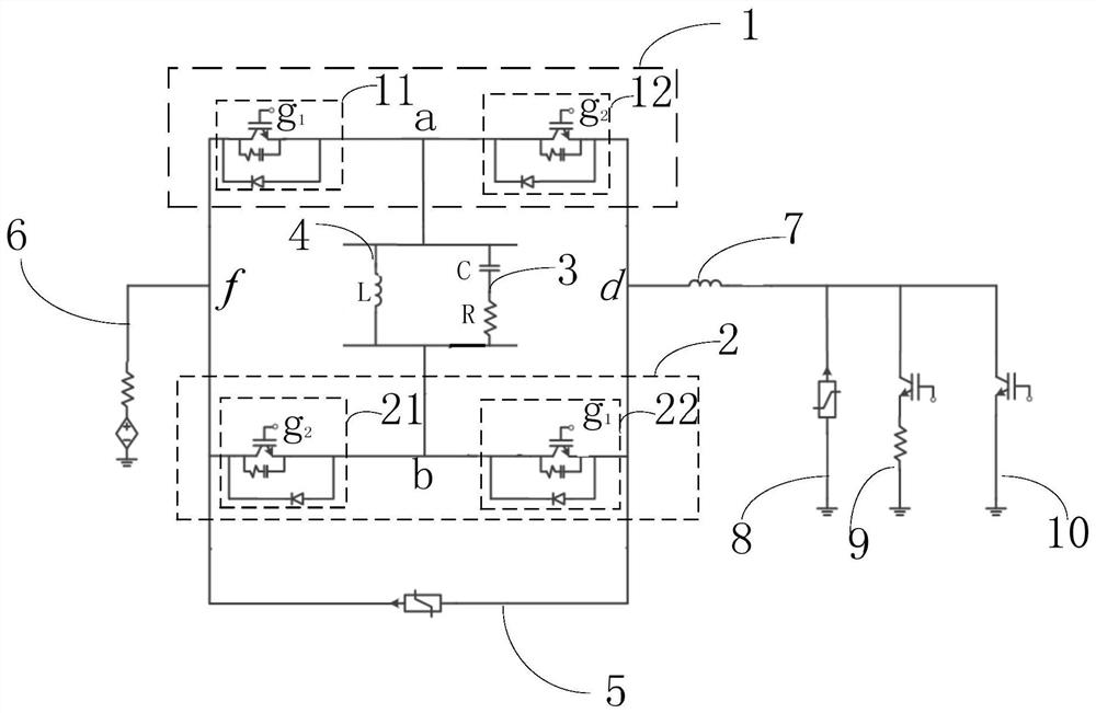
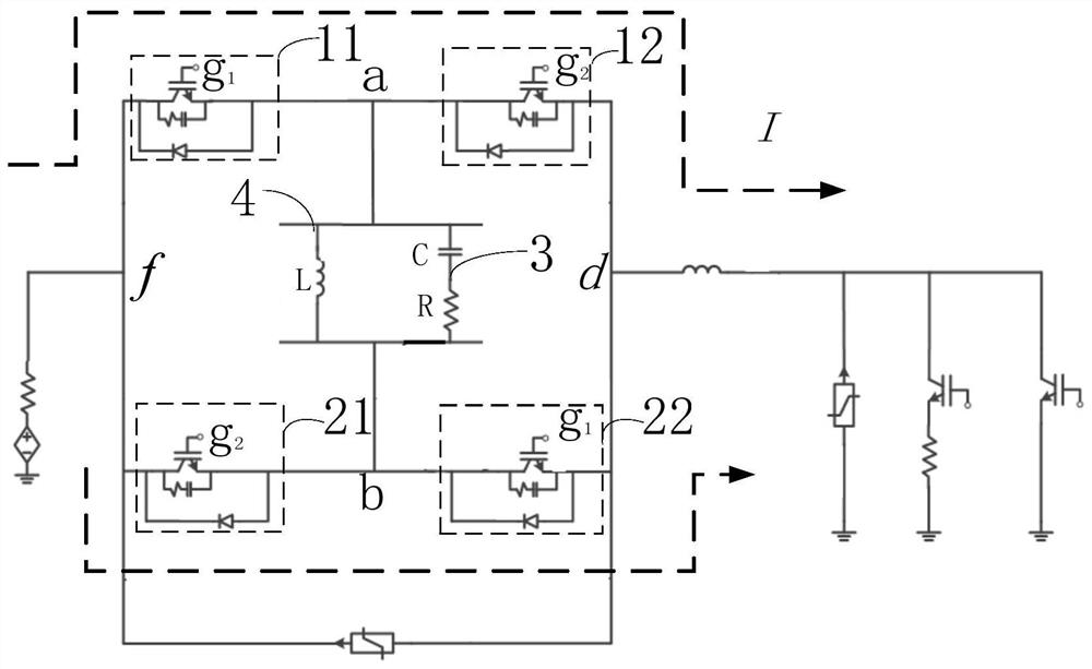
[0030] Such as figure 1 The schematic diagram of the topology of the DC current limiter shown includes: the first IGBT string 1, the second IGBT string 2 connected in parallel with the first IGBT string 1, the RC series branch 3 and the inductance branch 4, the first IGBT string 1 includes: a first IGBT structure 11 and a second IGBT structure 12 connected to the first connection point a with the first IGBT structure 11, and the second IGBT string 2 includes: a third IGBT structure 21 and connected to the third IGBT structure 21 at The fourth IGBT structure 22 at the second connection point b, the RC series branch 3 and the inductance branch 4 are connected in parallel, one end of the RC series branch 3 and one end of the inductance branch 4 are connected to the first connection point a, the RC series branch The other end of ...


PUM


Abstract

The invention provides a direct current limiter topological structure and a direct current limiter thereof, relates to the technical field of power electronic conversion of direct current distribution, and solves a problem that peak voltage is caused by sudden change of inductive current when an existing direct current limiter is applied. Each of the first IGBT string and the second IGBT string comprises two connected IGBT structures, an inductance branch and an RC series branch are connected between connection nodes of any two connected IGBT structures, the requirement for limiting the short-circuit current amplitude increase speed is met, meanwhile, the current change time can be delayed through the RC series branch, and the short-circuit current amplitude increase speed is reduced; Lossof a direct-current power distribution system caused by a voltage peak due to sudden change of current of an inductance branch is avoided, and uninterrupted power supply of the direct-current power distribution system to a load is ensured.

Description

technical field [0001] The invention relates to the technical field of power electronic conversion of DC power distribution, and more specifically, to a DC current limiter topology and the DC current limiter. Background technique [0002] In recent years, with the changes in the structure of power sources and loads, users have higher and higher requirements for power quality, which has brought great challenges to the AC power distribution system that has always occupied the mainstream of power distribution systems. With the continuous development of smart grids and With the increasing maturity of power electronics technology, people began to study DC power distribution methods. DC power distribution has a series of advantages such as large power supply capacity, low line loss, good power quality, and access to distributed power sources. [0003] The fault research of DC power distribution system is the basis of the development of DC power distribution technology. However, th...

Claims


Application Information

Patent Timeline
IPC IPC(8): H02H9/02
CPCH02H9/025
Inventor 范心明罗容波彭元泉李新刘益军王俊波孙广慧李国伟唐琪曾庆辉章涛宋安琪董镝黎小龙赵云云黎绍辉王宁刘剑琦周俊
Owner FOSHAN POWER SUPPLY BUREAU GUANGDONG POWER GRID
Why Eureka
Eureka Blog
Learn More