
Optical probe wireless charging device and wireless charging method thereof

A technology for wireless charging and rechargeable batteries, applied in circuit devices, battery circuit devices, current collectors, etc., can solve the problems affecting the sealing performance of optical probes, processing time and process interference, and high battery costs

Pending Publication Date: 2021-03-19
深圳市蓝蓝软件有限公司
View PDF0 Cites 0 Cited by
  • Summary
  • Abstract
  • Description
  • Claims
  • Application Information

AI Technical Summary

Problems solved by technology

[0003] However, the optical probe is powered by batteries, such as button batteries. During use, the short battery life of the optical probe has become an unavoidable problem. In current industrial applications, the continuous use time of the optical probe is usually two After two weeks, it needs to be shut down and replaced with a new battery to continue working
Stopping to replace the battery will interfere with the processing time and process flow. To replace the battery, the battery compartment cover of the optical probe needs to be removed. Since the battery life is generally two weeks, it means that there will be a lot of problems in the long production cycle. Frequent disassembly will affect the sealing performance of the optical probe, thereby affecting the measurement accuracy, and the battery needs to be replaced regularly to prevent the adverse impact on production caused by a sudden power shortage
In addition, the battery is an industrial battery, and the price is high, resulting in a high cost of replacing the battery. The final cost will be reflected in the product price, which affects the sales competitiveness of the product.

Method used


Image

  • Optical probe wireless charging device and wireless charging method thereof
  • Optical probe wireless charging device and wireless charging method thereof
  • Optical probe wireless charging device and wireless charging method thereof

Examples


Embodiment Construction

[0029] In order to make the technical problems, technical solutions and beneficial effects to be solved by the present invention clearer, the present invention will be further described in detail below in conjunction with the accompanying drawings and embodiments. It should be understood that the specific implementation manners described here are only used to explain the present invention, and are not intended to limit the present invention.

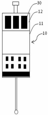
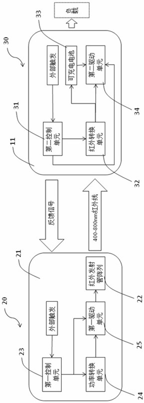
[0030] see Figure 1~Figure 5 , a wireless charging device for an optical probe according to an embodiment of the present invention includes an optical probe 10 , an infrared transmitting base station 20 and an infrared receiving device 30 .

[0031] The optical measuring head 10 is rotatable and includes a casing 11 on which a light-transmitting cover 12 through which infrared rays can pass is arranged. In this embodiment, the housing 11 is cylindrical, and the transparent cover 12 is ring-shaped.

[0032] Infrared transmitting base s...


PUM


Abstract

The invention discloses an optical measuring head wireless charging device, and the device comprises an optical measuring head, an infrared transmitting base station and infrared receiving equipment.The infrared transmitting base station comprises a base and an infrared transmitting tube array arranged on the base, and the infrared receiving equipment is arranged in a shell of the optical measuring head and comprises an infrared conversion unit and a rechargeable battery; the infrared conversion unit receives infrared light emitted by the infrared emitting tube array, converts light energy into voltage and current and charges the rechargeable battery. The invention further discloses a wireless charging method of the optical probe wireless charging device. The optical probe wireless charging device and the wireless charging method thereof have the advantages of being high in production and manufacturing efficiency, low in cost and good in sealing performance of optical equipment.

Description

technical field [0001] The invention relates to the field of machine tool processing, in particular to a wireless charging device for an optical probe used in machine tool processing and a wireless charging method thereof. Background technique [0002] CNC (full name Computerized Numerical Control Machine) is an optical probe for computer numerical control machine tools. It is installed on a CNC machine tool. It does not need human intervention in the processing cycle to directly measure the size and position of the tool or workpiece, and according to The measurement results automatically correct the position of the workpiece or tool, enabling the same machine tool to process parts with higher precision. As the dimensional accuracy and installation accuracy of parts are getting higher and higher, the measuring part of the probe is in a swing state when it is working, and a sealing structure is required to prevent water and fog inside the probe, so as to avoid the failure of ...

Claims


Application Information

Patent Timeline
IPC IPC(8): H02J50/30H02J50/90H02J7/00
CPCH02J50/30H02J50/90H02J7/0013H02J7/0068
Inventor 夏锴杨敖陈胜
Owner 深圳市蓝蓝软件有限公司
Learn More