Shell assembly and motor using same
A shell component and component technology, which is applied in the direction of electric components, electrical components, electromechanical devices, etc., can solve the problems of small effective contact length between the motor shaft and the motor shell, low fixing strength between the motor shaft and the motor shell, etc., and achieve improved Riveting fixation strength, large effective contact length, easy to match the effect of assembly in place
- Summary
- Abstract
- Description
- Claims
- Application Information
AI Technical Summary
Problems solved by technology
Method used
Image
Examples
Embodiment 1
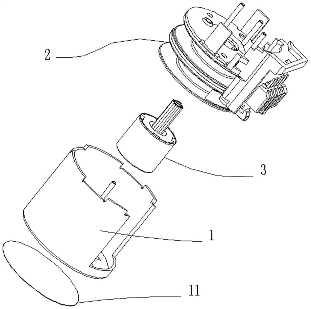
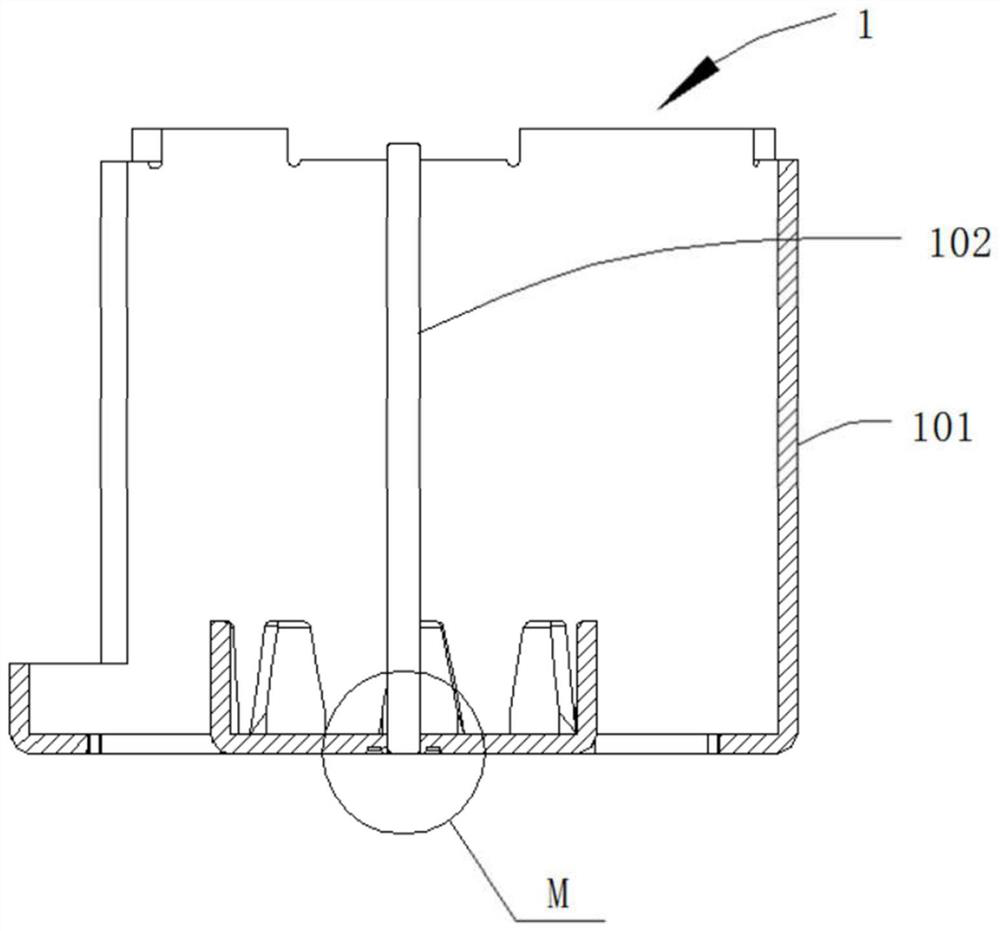
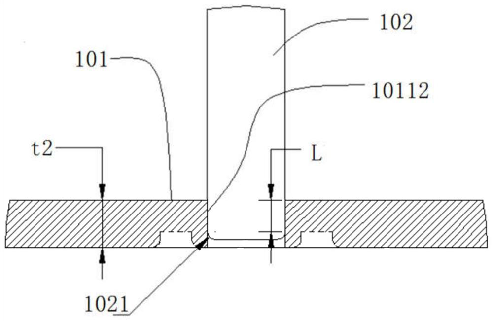
[0037] Example 1, such as Figure 4-Figure 7 As shown, a housing assembly includes a motor housing 101 and a motor shaft 102. The motor housing 101 is composed of a bottom plate 1011 and a side wall 1012 surrounding the bottom plate 1011 to form a barrel-shaped structure with an open end. The inside of the barrel-shaped structure A cavity is formed, the area where the cavity is located is the inside of the motor housing 101 or the side wall 1012, one end of the motor shaft 102 is provided with a chamfer 1021, and the center of the bottom plate 1011 protrudes toward the opening end of the motor housing 101 to form a step 10111, There is a shaft hole 10112 in the center of the step 10111, and one end of the motor shaft 102 provided with a chamfer 1021 is suitable for being inserted into the shaft hole 10112. The thickness t1 of the step is equal to the thickness t2 of the bottom plate.
[0038] The side wall 1012 extends upward from one side of the bottom plate 1011, and the sid...
Embodiment 2
[0045] Embodiment 2, on the basis of Embodiment 1, there is a first annular decompression groove 1013 at the junction of the bottom plate 1011 and the side wall 1012. Such as Figure 6 and Figure 10 As shown, the first annular decompression groove 1013 is located at the root of the side wall 1012, adhering to the inner wall of the side wall 1012, and the cross section of the first annular decompression groove 1013 is approximately rectangular. The principle of this design is: the sheet material 7 forms the side wall 1012 through the stretching process and the shaping process, and the stretching process is realized by the stretching die, including the stretching die 8a and the stretching punch 8b, in order to prevent the stretching process When the side wall 1012 is stretched and torn, a punch fillet transition area will be provided at the front end of the stretching punch 8b, and a transition fillet area 9 will be formed at the root of the side wall 1012. There is a certain...
Embodiment 3
[0046] Embodiment 3, on the basis of Embodiment 1 or Embodiment 2, a first decompression groove 1014 is provided at the junction of the bottom plate 1011 and the pole claw 10113 . Such as Figure 6 As shown, the structure of the first decompression groove 1014 is similar to that of the first annular decompression groove 1013, and the effect is the same. The difference from the first annular decompression groove 1013 is that the first decompression groove 1014 is the The corresponding number of arc slots.
[0047] The principle of setting the first decompression groove 1014 is: the material of the motor housing 101 is free-cutting steel, because the bending part of the pole claw 10113 has a certain internal stress, and the material itself has a certain elasticity, so punching and bending Afterwards, there will be a certain rebound, and at this time, the verticality between the pole claw 10113 and the bottom plate 1011 cannot be guaranteed; therefore, along the root of the pole...
PUM
 Abstract
Description
Claims
Application Information
 - R&D
- Intellectual Property
- Life Sciences
- Materials
- Tech Scout
- Unparalleled Data Quality
- Higher Quality Content
- 60% Fewer Hallucinations
Browse by: Latest US Patents, China's latest patents, Technical Efficacy Thesaurus, Application Domain, Technology Topic, Popular Technical Reports.
© 2025 PatSnap. All rights reserved.Legal|Privacy policy|Modern Slavery Act Transparency Statement|Sitemap|About US| Contact US: help@patsnap.com


