Improved lithium ion battery using high surface area nanotubes
A technology with high surface area and carbon nanotubes, which can be used in carbon nanotubes, organic electrolyte batteries, nanocarbons, etc., and can solve problems such as obstacles to the use of carbon nanotubes
- Summary
- Abstract
- Description
- Claims
- Application Information
AI Technical Summary
Problems solved by technology
Method used
Image

Examples
Embodiment 1
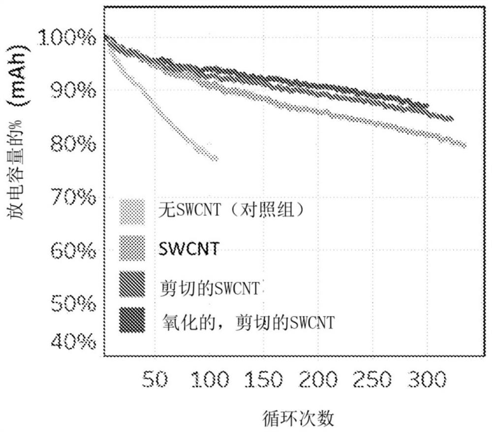
[0095] Example 1 - Oxidation of Tuball TM (OCSiAl)
[0096] Heat 35g of >64% nitric acid to 95°C. To this acid was added 15 g of pristine multi-walled carbon nanotubes (Tuball TM ). Primitive tubes have the morphology of tightly bundled tree trunks. While maintaining the solution at about 95°C for 5 hours, a mixture of acid and carbon nanotubes was mixed and labeled "oSWCNT-82-2". At the end of the reaction period, oSWCNT 82-2 was filtered to remove acid and washed with reverse osmosis (RO) water to pH 3-4. The resulting CNTs were oxidized to about 3.6% and contained about 4.4% metal residues.
[0097] Variations of this procedure were also performed using slightly different parameters, as shown in Table 1 below:
[0098] Sample oxidized by MAO process: e.g. 35g HNO 3 (65%) / 15g Tuball TM , Oxidation at 95°C.
[0099] 23.33g HNO 3 (65%) + 10.01 g CNTs. T = 95°C. Initial large NOx plume with CNT addition.
[0100] Table 1
[0101] time (h) T(℃) % oxi...
Embodiment 2
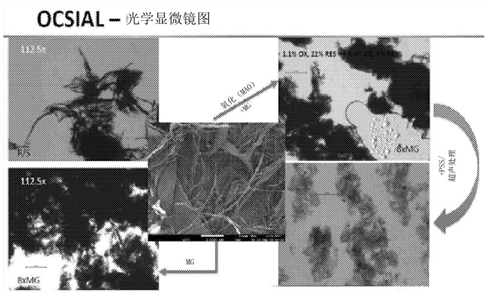
[0110] Example 2 - Shear Treatment of Non-Oxidized and Oxidized OCSiAl Tubes
[0111] Example 2A - Shear Treatment of Oxidized OCSiAl Tubes
[0112] Sample volume -1200 mL. Use a 1.5L stainless steel container for rotor / stator (R / S) work.
[0113] Oxidized OCSiAl ~ 0.15%
[0114] Oxidized OCSiAl source: 82-final (pH 3.61, 27.1% solids)
[0115] 1200g X 0.15% = 1.8g dry weight equivalent = 6.64g wet cake. 6.65g wet cake was used.
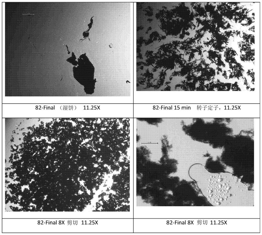
[0116] Check the viscosity through the rotor stator R / S as shown below.
[0117] T(min) T(℃) comment 0 23 5 31 Clear droplets on the plastic covering the opening of the container. non sticky 9 41 Clear droplets on the plastic covering the opening of the container. non sticky +6.62g wet cake 15 50 Viscous mixture. to cut
[0118] Place in the refrigerator for ~1.5h.
[0119] to cut
[0120]
[0121]
[0122] Sample Designation 180417-MF-1A (0.26% solids), 180417-MF-1B (0.22% so...
Embodiment 2B
[0127] Example 2B - Shear treatment of unmodified OCSiAl
[0128] 600 mL @ 0.4% solids = 2.4 g OCSiAl.
[0129] OCSiAl source: TUBALL TM single-walled carbon nanotubes. Batch No. 01RW01.N1.257 Date of Manufacture: December 20, 2016.
[0130] Rotor / Stator - performed in an 800 mL plastic container in an ice bath.
[0131] t(min) T(℃) comment 0 21 5 48 Higher viscosity than oxidized OCSiAl, 3% 10 65 Place in the refrigerator to cool for 50 minutes before cutting. This brought the temperature to 27°C.
[0132] Cut processing:
[0133]
[0134] Sample 180418-MF-1. 0.34% solids (17 g sample size) - 500 g recovered sample were measured.
[0135] Example 2C - Oxidized OCSiAl / MA14 by shearing device
[0136] MA 14 / oxidized OCSiAl was prepared in a ratio of 80 / 02. This was done to see if we could produce an infant by taking a wet cake of these two components, passing it through the rotor stator, and then shearing. Therefore, after ...
PUM
| Property | Measurement | Unit |
|---|---|---|
| thickness | aaaaa | aaaaa |
| length | aaaaa | aaaaa |
| length | aaaaa | aaaaa |
Abstract
Description
Claims
Application Information
 - R&D Engineer
- R&D Manager
- IP Professional
- Industry Leading Data Capabilities
- Powerful AI technology
- Patent DNA Extraction
Browse by: Latest US Patents, China's latest patents, Technical Efficacy Thesaurus, Application Domain, Technology Topic.
© 2024 PatSnap. All rights reserved.Legal|Privacy policy|Modern Slavery Act Transparency Statement|Sitemap