Bread production dryer with good drying effect

A technology of a dryer and a drying mechanism, applied in the field of small bread, can solve the problems of low output and low work efficiency, and achieve the effects of high automation, continuous output of automation, and improved baking effect.

Active Publication Date: 2021-03-23
阜阳市家居乐食品有限公司
View PDF9 Cites 3 Cited by
  • Summary
  • Abstract
  • Description
  • Claims
  • Application Information

AI Technical Summary

Problems solved by technology

[0005] The purpose of the present invention is to address the deficiencies of the prior art, by arranging a packaging mechanism to cooperate with a transmission mechanism, so that a batch of bread is automatically output in rows during the transmission process, and can be automatically stacked in the vertical direction after the output work. After the stacking is completed, the lower bagging component is driven to automatically open the bag for packaging. The entire production line is highly automated and continuously output, which improves the output, thus solving the problem of manually stacking the bread in the bag when the old bread is packaged. The technical problems of low work efficiency and low output after putting in sequentially

Method used


Image

  • Bread production dryer with good drying effect
  • Bread production dryer with good drying effect
  • Bread production dryer with good drying effect

Examples


Embodiment 1

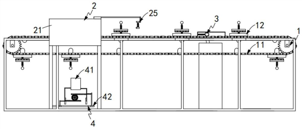
[0072] Such as figure 1 As shown, a dryer for small bread production with good drying effect, including:

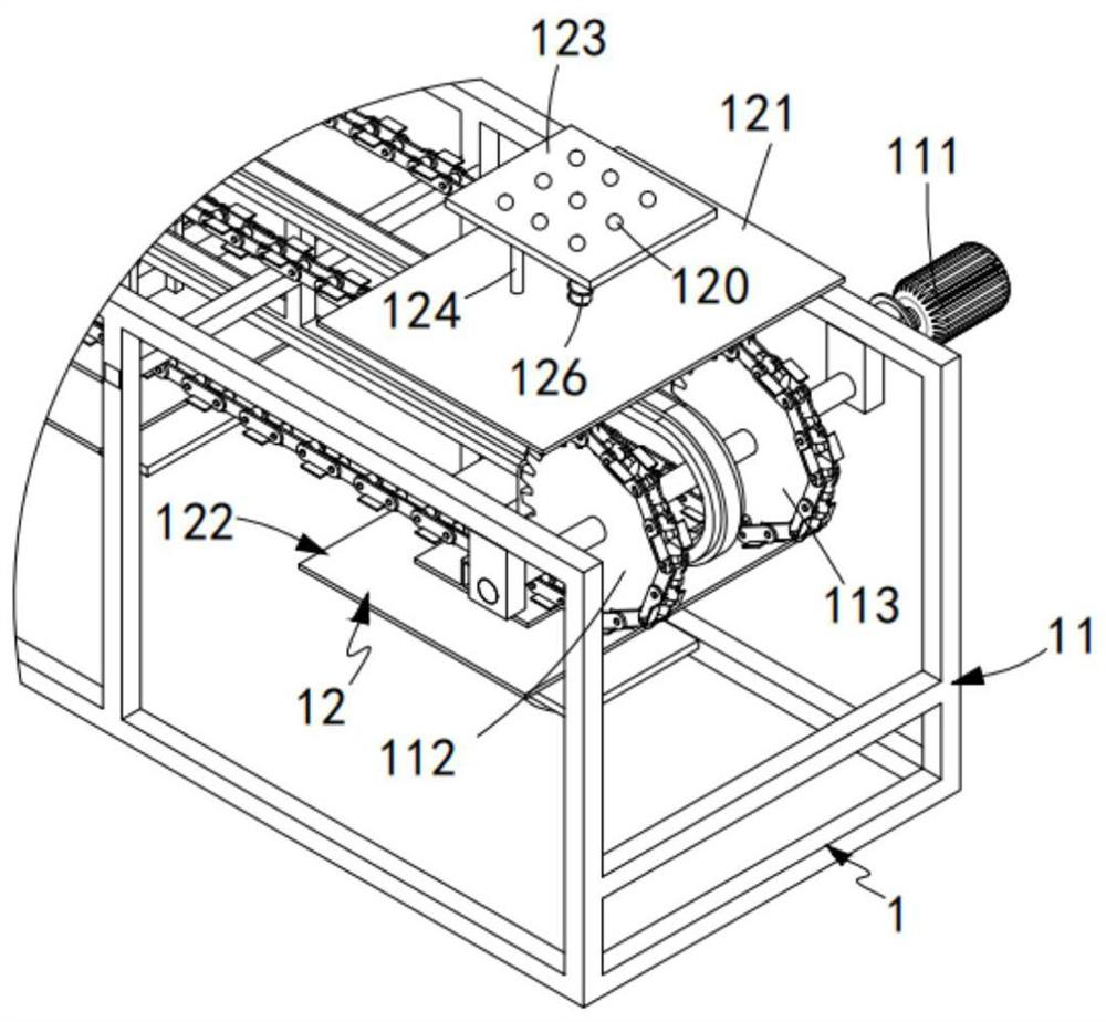
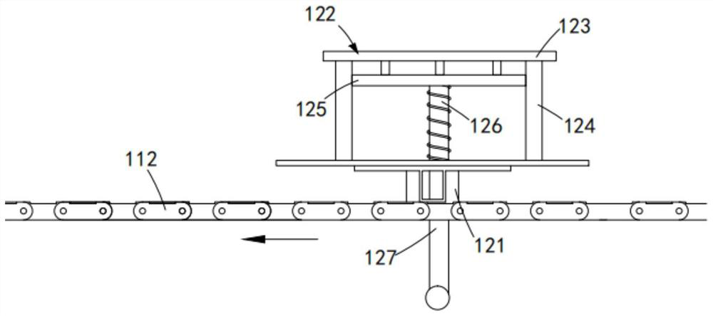
[0073] A transmission mechanism 1, the transmission mechanism 1 comprising a first transmission assembly 11 and several groups of bearing assemblies 12 equidistantly arranged on the first transmission assembly 11;

[0074] Drying mechanism 2, the drying mechanism 2 includes a drying box 21 sleeved outside the transmission mechanism 1, a positioning assembly 22 arranged at the input end of the drying box 21, and a positioning assembly 22 arranged in the drying box 21 And the first sub-assembly 23 for lateral sub-assembly, two sets of clamping assemblies 24 symmetrically arranged on both sides of the sub-assembly, and the clamping assembly 24 arranged outside the drying box 21 and cooperating with the clamping assembly 24 The second sub-assembly 25 for longitudinal sub-division work;

[0075] Injection mechanism 3, which is arranged outside the drying box 21 and arranged ...

Embodiment 2

[0115] Such as Figure 17 As shown, the components that are the same as or corresponding to those in the first embodiment are marked with the corresponding reference numerals in the first embodiment. For the sake of simplicity, only the differences from the first embodiment will be described below. The difference between this embodiment two and embodiment one is:

[0116] further, such as Figure 17 As shown, the center injection mechanism 3 includes an injection assembly 31 intermittently connected to the clamping assembly 24 and a rotating assembly 32 for driving the injection assembly 31 to perform centrifugal spraying;

[0117] The spraying assembly 31 includes a connecting pipe 311 arranged on the support plate 2424 with a magnetic connection end, a jam box 312 arranged on one side of the second transmission assembly 241 and communicating with the jam box 312 The hose 313, the electromagnetic ring 314 sleeved at the end of the hose 313, the electromagnetic ring 314 is s...


PUM


Abstract

The invention relates to a bread production dryer with a good drying effect, which comprises a transmission mechanism, the transmission mechanism comprises a first transmission assembly and a bearingassembly; a drying mechanism which comprises a drying box, a positioning assembly, a first direction dividing assembly, wherein two sets of clamping assemblies symmetrically arranged on the two sidesof the direction dividing assembly, and a second direction dividing assembly arranged outside the drying box and matched with the clamping assemblies to conduct longitudinal direction dividing work; acore injection mechanism; and a packaging mechanism which comprises a bearing assembly arranged below the first transmission assembly and a bagging assembly arranged below the bearing assembly and used for packaging bread output from the bearing assembly. The technical problems that when old bread is packaged, the bread needs to be stacked in a bag manually, placed in sequence and then packaged,the working efficiency is low, and the yield is low are solved.

Description

technical field [0001] The invention relates to the technical field of small bread, in particular to a drying machine for producing small bread with good drying effect. Background technique [0002] Bread drying is an indispensable part of the bread processing process. The quality of drying directly affects the taste of bread, and the quality assurance must be guaranteed through the dryer. The performance of the bread dryer affects the quality of bread. Ordinary The structure of the traditional bread dryer is more complicated, which makes the assembly or disassembly more troublesome, time-consuming and labor-intensive, and leads to the low efficiency of the dryer. The drying method of the ordinary dryer is relatively simple, which affects the drying efficiency. The amount of bread to be dried temporarily is small, which makes the work efficiency low, and ordinary dryers are fixed in a certain place, which does not meet the requirements of modern enterprises for machine flexi...

Claims


Application Information

Patent Timeline
Patent Type & Authority Applications(China)
IPC IPC(8): A47J37/08A21C9/06A21B1/42A21B3/00
CPCA21D13/00A47J37/08A47J37/0857A47J37/0871
Inventor 陈随奈
Owner 阜阳市家居乐食品有限公司
Why Eureka
Try Eureka