Composite conical section forming die pressurized by using soft die

A composite material and molding die technology, used in applications, household components, household appliances, etc., can solve the problems of pressure rise, inability to accurately control pressure, hinder the free expansion of rubber, etc., to improve the degree of compaction and avoid the overall pressure. The effect of uniform and uniform pressure

Active Publication Date: 2021-03-23
SHANGHAI COMPOSITES SCI & TECH CO LTD
View PDF8 Cites 3 Cited by
  • Summary
  • Abstract
  • Description
  • Claims
  • Application Information

AI Technical Summary

Problems solved by technology

However, in order to ensure the precise positioning of the soft rubber mold in this patent, positioning steel plates and metal blocks are used to limit the position of the soft mold, which hinders the free expansion of the rubber, and causes the molding pressure of the composite material to be mainly determined by the pressure generated by the thermal expansion effect of the rubber, that is, the pressure increases with the temperature. rise linear rise
In the autoclave process, it is impossible to achieve precise control of the pressure at multiple specific temperature points

Method used


Image

  • Composite conical section forming die pressurized by using soft die
  • Composite conical section forming die pressurized by using soft die
  • Composite conical section forming die pressurized by using soft die

Examples


Embodiment 1

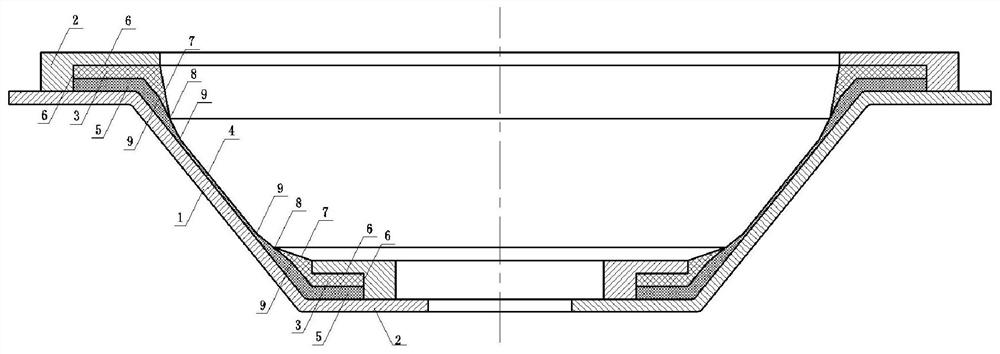
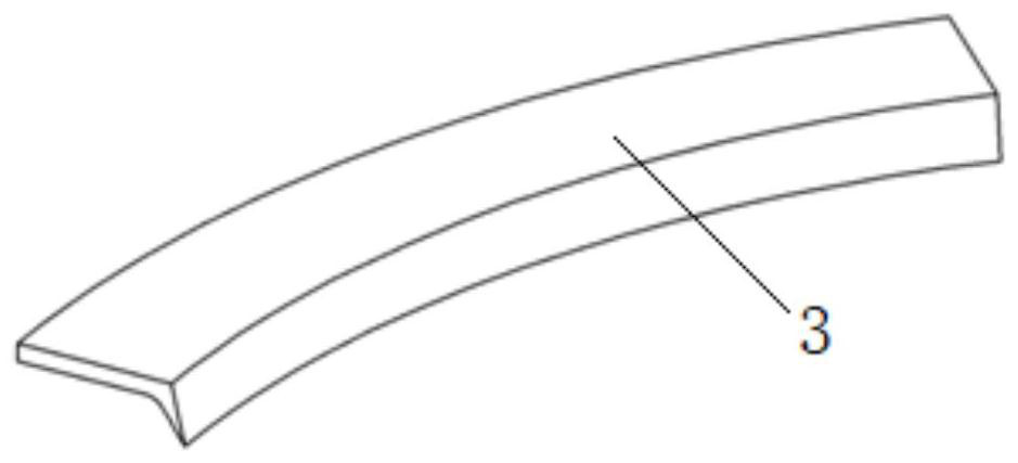
[0034] This embodiment relates to a kind of composite material cone segment molding die that uses soft mold pressurization, such as figure 1 As shown, it includes mold main body 1, rigid outer mold 2 and rubber soft mold 3;

[0035] The mold body 1 is used to support the product 4 to be laid up and cured with prepreg.

[0036] The rigid outer mold 2 is arranged on the end of the mold body 1 and the soft rubber mold 3 to limit the flange end of the product 4 and limit the expansion of the soft rubber mold 3 so that all the expansion is released to the inner surface 7 . The mold of this embodiment is provided with a rigid outer mold 2 limit on the outer surface 6 of the soft rubber mold 3; the inner surface 7 of the soft rubber mold 3 has no rigid outer mold 2 limit, which is used as a pressure relief surface in the curing process to make the soft rubber mold 3 expand. The pressure is consistent with the pressure in the autoclave.

[0037] The soft rubber mold 3 is set on the ...

Embodiment 2

[0049] This embodiment relates to a kind of composite material cone segment molding die that uses soft mold pressurization, such as Figure 5 As shown, it includes mold main body 1, rigid outer mold 2 and rubber soft mold 3;

[0050] The mold body 1 is used to support the product 4 to be laid up and cured with prepreg.

[0051] The rigid outer mold 2 is set on the end of the mold main body 1 and the soft rubber mold 3 to limit the flange end of the product 4 and limit the expansion of the soft rubber mold 3, so that the expansion can release pressure to the inner surface 7 and the outer side Face 10 is released.

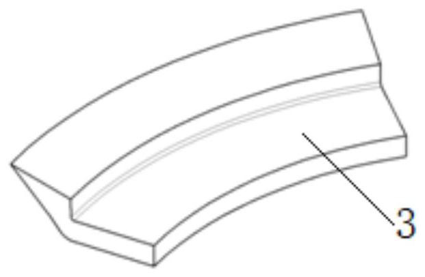
[0052] And, different from Example 1, in order to better avoid fiber buckling, the outer side pressure relief surface 10 without steel mold constraints is arranged at intervals on the lateral outer side 6 of the soft rubber mold 3 of this embodiment (the outer side pressure relief surface 10 is not the whole circle); as in Image 6 shown. This setting enables the...


PUM


Abstract

The invention discloses a composite conical section forming die pressurized by using a soft die. The forming die comprises a rubber soft die arranged between a die main body and a rigid outer die, andthe rubber soft die is used for pressurizing a composite prepreg section which corresponds to a flange thickening area and is laid on the die main body in the forming process. The rigid outer die isarranged at the exterior of the rubber soft die for limitation, and the inner side of the rubber soft die is a pressure relief surface, so that the expansion pressure of the soft die is consistent with the internal pressure of an autoclave; furthermore, the rubber soft die is formed by splicing circumferential sections, and forming pressure loss caused by internal tension of rubber in the pressingprocess is eliminated; and moreover, the inner side edge of the rubber soft die is located in the center of a wall thickness gradient area, so that a process boundary and a design boundary are staggered, and edge fiber buckling of the thickening area is avoided. In conclusion, the solid rubber soft die is designed for pressurization, and the problem that a large-wall-thickness corner position ofthe composite conical section is hard to compact is solved.

Description

technical field [0001] The invention relates to a composite material cone section forming die, in particular to a composite material cone section forming die pressurized by a soft mold. Background technique [0002] At present, a large number of high-strength composite materials are used in the load-bearing structure of aerospace launch vehicles. The main advantage of composite materials is that composite materials have a good weight reduction effect and can increase the payload of a single launch. As an important load-bearing structure of the final stage power cabin of the rocket body, the composite cone section is used to support payloads such as satellites. The typical structure of the composite material cone section is a thin-walled cone section, with thickened flanges at the front and rear ends, and a wall thickness transition zone between the flange and the cone section. In order to improve the strength of the interface on the flange, the thickness of the flange wall ...

Claims


Application Information

Patent Timeline
Patent Type & Authority Applications(China)
IPC IPC(8): B29C33/40B29C70/34B29L31/30
CPCB29C33/405B29C70/342B29L2031/3097
Inventor 徐云研曹恒秀柯常宜张志斌赵丁丁夏海祥蔡克甲叶周军张兵章宇界张砚达史文锋余娜
Owner SHANGHAI COMPOSITES SCI & TECH CO LTD
Why Eureka
Try Eureka