Material pulling type film tearing mechanism

A film and film knife technology, applied in the direction of layered products, lamination, etc., can solve the problems of low degree of automation, low work efficiency, time-consuming and laborious, etc., and achieve the effect of high degree of automation, improved production efficiency, and improved film tearing efficiency.

Pending Publication Date: 2021-03-23
SUZHOU RS TECH
View PDF14 Cites 4 Cited by
  • Summary
  • Abstract
  • Description
  • Claims
  • Application Information

AI Technical Summary

Problems solved by technology

[0003] The film on the surface of the workpiece needs to be removed during the processing. The existing film tearing device removes the film on the surface of the workpiece by manpower. As a periodic work, it is time-consuming and laborious, with low automation and low work efficiency.

Method used


Image

  • Material pulling type film tearing mechanism
  • Material pulling type film tearing mechanism
  • Material pulling type film tearing mechanism

Examples


Embodiment Construction

[0040] The technical solutions in the embodiments of the present invention will be clearly and completely described below in conjunction with the accompanying drawings in the embodiments of the present invention. Obviously, the described embodiments are only part of the embodiments of the present invention, not all of them. Based on the implementation methods in the present invention, all other embodiments obtained by persons of ordinary skill in the art without making creative efforts belong to the protection scope of the present invention.

[0041] In the drawings, the shapes and dimensions may be exaggerated for clarity, and the same reference numerals will be used throughout to designate the same or like parts.

[0042] Unless otherwise defined, the technical terms or scientific terms used herein shall have the usual meanings understood by those skilled in the art to which the present invention belongs. "First", "second" and similar words used in the patent application spe...


PUM


Abstract

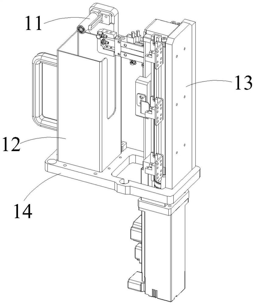
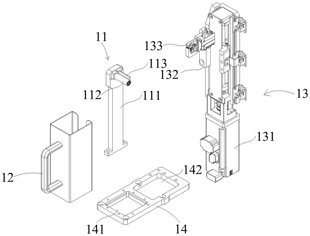
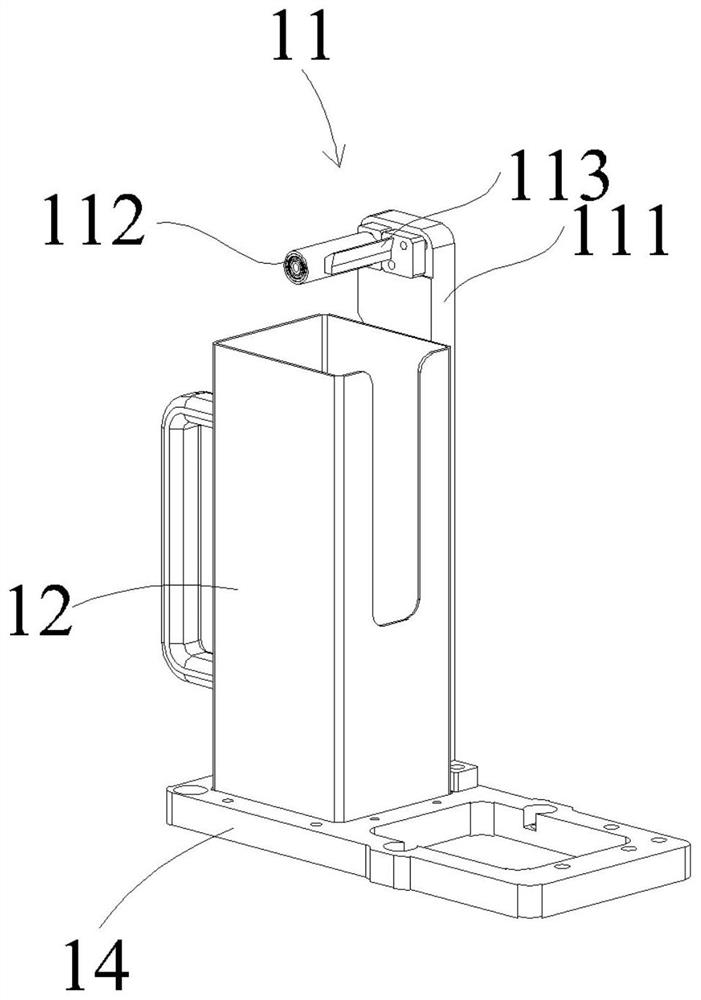
The invention discloses a material pulling type film tearing mechanism which comprises a workpiece bearing module used for bearing a film to be torn, a recycling material box arranged beside the workpiece bearing module, and a material pulling and film tearing assembly arranged beside the recycling material box, wherein the material pulling and film tearing assembly comprises a lifting driving module arranged in a vertical direction, a fixed plate in transmission connection with a movable part of the lifting driving module, and a clamping module fixedly connected to the surface of the fixing plate; and the clamping module clamps a thin film on the surface of a workpiece, and the lifting driving module drives the clamping module to do reciprocating motion in the vertical direction so as tocontrol the clamping module to tear the film on the workpiece and put the film into the recycling material bin. According to the film tearing mechanism, the structure is simple, the layout is reasonable, the automation degree is high, the film tearing efficiency of workpieces is greatly improved, and finally the production efficiency is improved.

Description

technical field [0001] The invention relates to the field of non-standard automation. More specifically, the present invention relates to a pull-type film tearing mechanism. Background technique [0002] In the field of non-standard automation, it is well known that film tearing devices with different structures are used to remove the film on the surface of the workpiece. In the process of researching and realizing the removal of the workpiece surface film, the inventor found that the film tearing device in the prior art has at least the following problems: [0003] The film on the surface of the workpiece needs to be removed during the processing. The existing film tearing device removes the film on the surface of the workpiece by manpower. As a periodic work, it is time-consuming and laborious, with low automation and low work efficiency. [0004] In view of this, it is necessary to develop a pull-type film tearing mechanism to solve the above-mentioned problems. Conte...

Claims


Application Information

Patent Timeline
Patent Type & Authority Applications(China)
IPC IPC(8): B32B43/00
CPCB32B43/006
Inventor 缪磊司观义韩龙丁俊
Owner SUZHOU RS TECH
Why Eureka
Try Eureka