
A self-protection device for a new energy battery and its application method

A self-protection and new energy technology, applied in the direction of secondary batteries, battery components, circuits, etc., can solve the problems of heat consumption and speed up heat, reduce the probability of being damaged, speed up heat dissipation, and have a good protective effect Effect

Active Publication Date: 2021-07-16
深圳市帕德新能源有限公司
View PDF3 Cites 0 Cited by
  • Summary
  • Abstract
  • Description
  • Claims
  • Application Information

AI Technical Summary

Problems solved by technology

[0005] In view of the problems existing in the prior art, the object of the present invention is to provide a self-protection device for a new energy battery and its application method, which can firstly disperse the heat at the welding point evenly at the bottom of the battery pack, and pass the U-shaped The heat distribution network disperses the heat to the surface of the shell, which significantly reduces the heat accumulation at the welding point compared with the existing technology, effectively protecting the battery pack from local overheating, thereby reducing potential safety hazards and prolonging its service life. Under the action of the point, on the one hand, the internal buffer ball can play a buffering role, reducing the probability of battery pack damage in case of accidental impact; The speed at which heat is dissipated from the shell, combined with the function of the moisture-absorbing heat-consuming block, can not only consume heat, but also absorb moisture, effectively maintaining a dry and safe environment when the battery pack is in use

Method used


Image

  • A self-protection device for a new energy battery and its application method
  • A self-protection device for a new energy battery and its application method
  • A self-protection device for a new energy battery and its application method

Examples


Embodiment 1

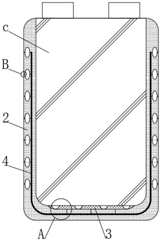
[0045] see figure 1 , c in the figure represents a battery pack, a self-protection device for a new energy battery, including a heat-conducting layer 3 arranged at the welding point at the lower end of the battery pack, the heat-conducting layer 3 is located in the casing 2, and a U-shaped thermal network is embedded in the casing 2 4.

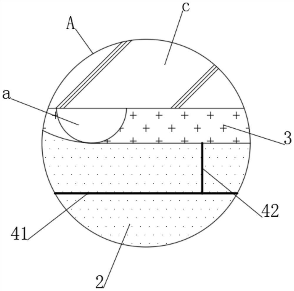
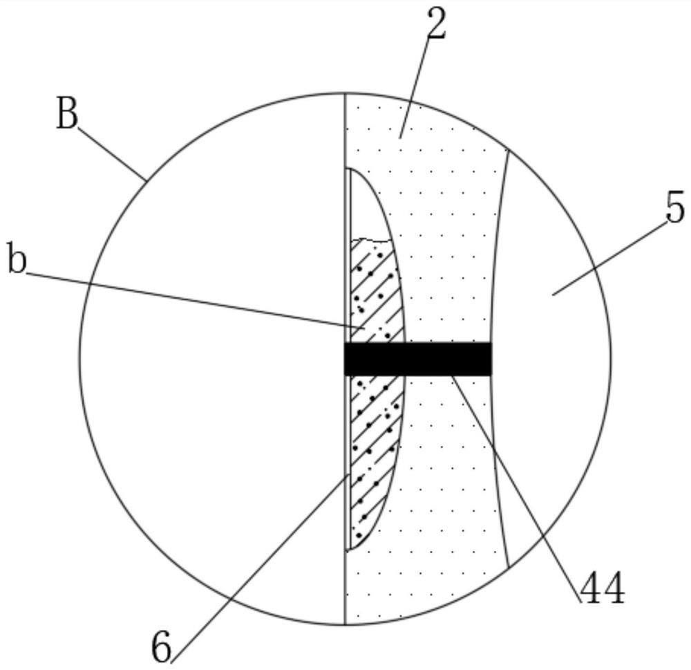
[0046] see Figure 2-4 In the figure, a represents the welding point, b represents the moisture-absorbing heat dissipation block, and the U-shaped sub-heating network 4 includes a plurality of longitudinal heat-conducting columns 42 fixedly connected with the heat-conducting layer 3, and a U-shaped heat-conducting sheet 41 embedded in the shell 2 in a U-shape , a plurality of inner heat conduction columns 43 fixedly connected to the outer ends of the U-shaped heat conduction sheet 41 and a plurality of outer heat conduction columns 44 corresponding to the inner heat conduction columns 43, and a double protection point 5 is arranged between th...


PUM


Abstract

The invention discloses a self-protection device for a new energy battery and a method for using the same, belonging to the field of new energy batteries. A self-protection device for a new energy battery can firstly disperse the heat at the welding point evenly on the bottom of the battery pack, And through the U-shaped heating network to disperse the heat to the surface of the shell, compared with the existing technology, the heat accumulation at the welding point is significantly reduced, and the battery pack is effectively protected from local overheating, thereby reducing safety hazards and prolonging its service life. At the same time, under the action of double protection points, on the one hand, the inner buffer ball can play a buffering role, reducing the probability of battery pack damage in case of accidental impact; , and then significantly accelerate the speed of heat dissipated from the outer shell, and at the same time cooperate with the function of the moisture-absorbing heat-consuming block, which can not only consume heat but also absorb moisture, effectively maintaining a dry and safe environment when the battery pack is in use.

Description

technical field [0001] The invention relates to the field of new energy batteries, and more specifically, to a self-protection device for new energy batteries and a method for using the same. Background technique [0002] In the current new energy industry, especially in the field of power batteries, lithium-ion batteries have gained a great advantage due to their high energy density, long cycle life, and no memory effect in charging and discharging, and have become the new energy vehicle powertrain. the only solution. Among them, round batteries and square batteries have always been two different directions. Especially for passenger cars represented by Tesla, they are more inclined to use cylindrical batteries. In the early stage, standard 18650 batteries were mainly used. At the same time, 21700 batteries are also developing rapidly as an emerging round battery generation. The energy density of the developed battery module and battery pack system is about 300Wh / kg, which...

Claims


Application Information

Patent Timeline
Patent Type & Authority Patents(China)
IPC IPC(8): H01M50/258H01M50/242H01M50/244H01M10/613H01M10/617H01M10/653H01M10/655
CPCH01M10/613H01M10/617H01M10/653H01M10/655Y02E60/10
Inventor 张舒德
Owner 深圳市帕德新能源有限公司
Learn More