High-precision punch forming die for ceiling crossbeam in bullet train carriage

A technology of stamping and forming inside the carriage, which is applied in the field of high-precision stamping and forming moulds for the ceiling beams in the carriage of the motor train, which can solve the problems of no precise positioning, no fixing function, no auxiliary pick-up and so on.

Pending Publication Date: 2021-03-26
盐城市富源引擎科技有限公司
View PDF12 Cites 2 Cited by
  • Summary
  • Abstract
  • Description
  • Claims
  • Application Information

AI Technical Summary

Problems solved by technology

[0006] The purpose of the present invention is to provide a high-precision stamping and forming mold for the ceiling beam in the motor car compartment, so as to solve the problems in the above-mentioned background technology that do not have the function of precise positioning, do not have the function of fixing and do not have the function of auxiliary pick-up

Method used


Image

  • High-precision punch forming die for ceiling crossbeam in bullet train carriage
  • High-precision punch forming die for ceiling crossbeam in bullet train carriage
  • High-precision punch forming die for ceiling crossbeam in bullet train carriage

Examples


Embodiment 1

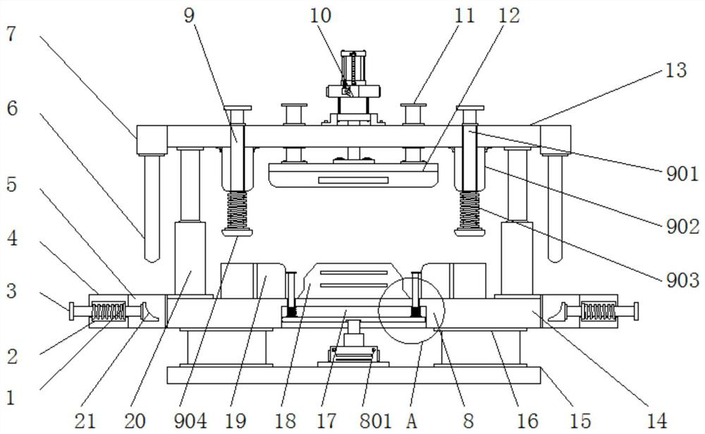
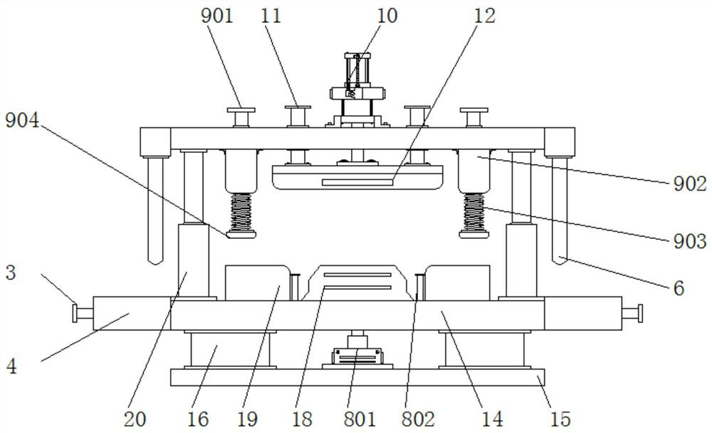
[0027] Example 1: See Figure 1-4 , a high-precision stamping and forming mold for the ceiling beam in the motor car compartment, including a bottom plate 15, and also includes an ejection structure 8 that is convenient for taking parts, a fixing structure 9 that prevents the workpiece from shifting, and a positioning structure that ensures the normal operation of the device;

[0028] The both sides of base plate 15 tops are all provided with two supporting feet 16, and the top of supporting feet 16 is provided with support plate 14, and the top middle position of support plate 14 is equipped with lower mold base 18, and the supporting plate of lower mold base 18 both sides A side plate 19 is installed on the top of 14, and an empty slot 17 is provided at the central position of the bottom end of the support plate 14, and the ejection structure 8 is arranged inside the empty slot 17;

[0029] The top of the support plate 14 on one side of the side plate 19 is provided with two...

Embodiment 2

[0034] Embodiment 2: The ejector structure 8 includes a first cylinder 801, a push rod 802, an auxiliary spring 803 and a horizontal plate 804. The first cylinder 801 is arranged at the top center of the bottom plate 15. The model of the first cylinder 801 can be SC63 , and the top of the first cylinder 801 extends to the inside of the cavity 17, a horizontal plate 804 is arranged horizontally inside the cavity 17 above the first cylinder 801, and both sides of the top of the horizontal plate 804 are provided with push rods 802, the cavity The outer wall of the push rod 802 between 17 and the horizontal plate 804 is provided with an auxiliary spring 803, and the top and bottom ends of the auxiliary spring 803 are welded to the hollow groove 17 and the horizontal plate 804 respectively;

[0035] The top ends of the ejector pins 802 all extend to the top of the support plate 14, and the ejector pins 802 are all arranged between the lower mold base 18 and the side plate 19;

[00...

Embodiment 3

[0037] Embodiment 3: The fixed structure 9 includes an extension rod 901, a fixed seat 902, a buffer spring 903 and a pressing plate 904. The fixed seat 902 is arranged at the bottom of the top plate 13 on both sides of the upper mold base 12, and the bottom of the fixed seat 902 is provided with Extension rod 901, the bottom end of extension rod 901 is equipped with pressing plate 904, and the outer wall of extension rod 901 between pressing plate 904 and fixed seat 902 is all sleeved with buffer spring 903, and the top and bottom end of buffer spring 903 are connected with the fixed seat respectively. 902 and pressing plate 904 are welded;

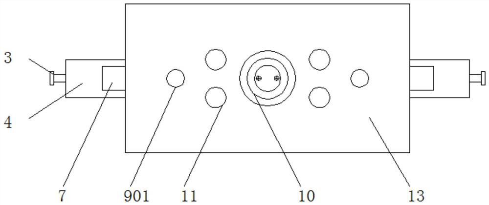
[0038] The top end of the extension rod 901 runs through the inside of the fixing seat 902 and the top plate 13, and the top end of the extension rod 901 extends to the top of the top plate 13;

[0039] Specifically, such as figure 1 , figure 2 and image 3 As shown, when using this mechanism, the pressing plate 904 is displaced down...


PUM


Abstract

The invention discloses a high-precision punch forming die for a ceiling crossbeam in a bullet train carriage. The high-precision punch forming die comprises a bottom plate and further comprises an ejection structure facilitating part taking, a fixing structure preventing a workpiece from deviating and a positioning structure guaranteeing normal work of a device, two supporting legs are arranged on each of the two sides of the top end of the bottom plate, and a supporting plate is arranged at the top ends of the supporting legs. A lower die base is installed in the middle of the top end of thesupporting plate, side plates are installed in the positions, on the two sides of the lower die base, of the top end of the supporting plate, an empty groove is formed in the center of the bottom endof the supporting plate, the ejection structure is arranged in the empty groove, two third air cylinders are arranged in the position, on one side of each side plate, of the top end of the supportingplate, and top plates are mounted at the top ends of the third air cylinders. A first air cylinder is started to work, thus a transverse plate can be pushed to move, an ejector rod moves upwards, anauxiliary spring deforms till the ejector rod ejects out a machined part, and the structure is beneficial to relieving the burden of workers.

Description

technical field [0001] The invention relates to the technical field of moulds, in particular to a high-precision stamping and forming mold for ceiling beams in motor vehicle compartments. Background technique [0002] Stamping die is a special process equipment for processing materials into parts. Stamping is a pressure processing method that uses a mold installed on a press to apply pressure to the material at room temperature to cause separation or plastic deformation to obtain the required parts. And the high-precision stamping and forming mold of the ceiling beam in the existing motor car compartment also has many deficiencies. [0003] First, the traditional beam high-precision stamping mold does not have the function of precise positioning, and the long-term working device is prone to deviation, resulting in unqualified production quality; [0004] Second, the traditional beam high-precision stamping mold does not have a fixed function, which makes it easy for the wo...

Claims


Application Information

Patent Timeline
Patent Type & Authority Applications(China)
IPC IPC(8): B21D37/10B21D22/02B21D43/00B21D45/02B21D53/88B21C51/00
CPCB21D37/10B21D22/02B21D43/003B21D45/02B21D53/88B21C51/00
Inventor 袁加付左四志
Owner 盐城市富源引擎科技有限公司
Why Eureka
Try Eureka