AI technical title is built by Patsnap AI team. It summarizes the technical point description of the patent document.
A technology of precision casting and mold shell, applied in the field of metallurgy, can solve problems such as high personnel requirements and unfavorable product uniformity, and achieve the effects of improving production efficiency, controlling casting quality in real time, and shortening casting time.
Active Publication Date: 2021-05-11
SHANGHAI LIGOU SENSOR SCI & TECH
View PDF6 Cites 0 Cited by
Summary
Abstract
Description
Claims
Application Information
AI Technical Summary
This helps you quickly interpret patents by identifying the three key elements:
Problems solved by technology
Method used
Benefits of technology
Problems solved by technology
In addition, in the existing technology, parameters such as lifting speed, lifting position, and reciprocating time are often set through the experience of operators, which requires high personnel, and there is no unified quantification of parameters such as the lifting speed, lifting position, and reciprocating time of smelting material mold shells. standard, which is not conducive to improving product uniformity
Method used
Image
Click on the blue label to locate the original text in one second.
Reading with bidirectional positioning of images and text.
Examples
no. 1 example ;
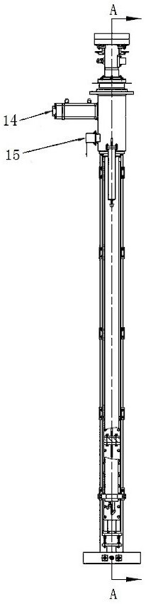
[0073] Such as figure 1 to combine figure 2 Shown, the present invention a kind of vacuum investment casting furnace formwork hoisting device, comprises:
[0074] Fixing piece 1, which passes through and is fixed on the bottom wall of the ingot cavity;
[0075] Main shaft 2, one end of which penetrates into the fixed part 1, and the other end is located outside the ingot cavity, which can move vertically in the fixed part 1 deep into or withdrawn from the ingot cavity;
[0076] The first sealing assembly is located in the ingot cavity and arranged between the fixed part 1 and the main shaft 2;
[0077] The second sealing assembly, which is located in the ingot cavity, is fixed between the fixing part 1 and the high temperature resistant telescopic protective cover 21;
[0078] Support frame 7, which is located outside the ingot cavity, is arranged in a vertical direction, and its upper part is fixed on the fixture 1;
[0079] The power source 14 is fixed on the top of the...
no. 2 example ;
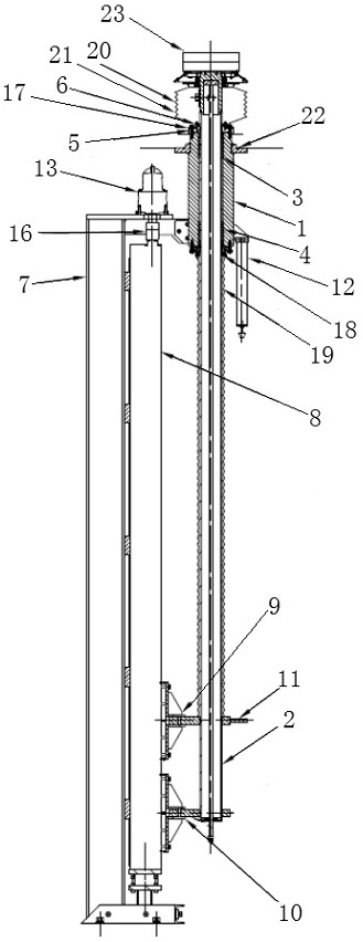
[0091] continue to refer figure 1 to combine figure 2 Shown, the present invention a kind of vacuum investment casting furnace formwork hoisting device, comprises:
[0092] Fixing piece 1, which passes through and is fixed on the bottom wall of the ingot cavity;
[0093] Main shaft 2, one end of which penetrates into the fixed part 1, and the other end is located outside the ingot cavity, which can move vertically in the fixed part 1 deep into or withdrawn from the ingot cavity;
[0094] The first sealing assembly is located in the ingot cavity and is arranged between the fixed part 1 and the main shaft 2, including the sealing ring positioning gasket 3 fixed in the fixed part 1 and the shaft sealing ring 4, and sleeved on the fixed part 1 The dust-proof sealing ring 18 of two ports, the dust-proof ring retaining ring 6 covers are contained on the dust-proof sealing ring 18;
[0095] The second sealing assembly, which is located in the ingot cavity, is fixed between the fi...
PUM
Abstract
The invention discloses a vacuum precision casting furnace mold shell lifting device, comprising: a fixing part is fixed on the bottom wall of an ingot cavity, a main shaft can move vertically in the fixing part, and a first sealing assembly is arranged between the fixing part and the main shaft Between, the second sealing assembly is fixed between the fixing part and the high temperature resistant telescopic protective cover, the upper part of the supporting frame is fixed on the fixing part, the power source is fixed on the upper part of the supporting frame, and the first fixing bracket is fixed on the supporting frame for connecting the main shaft and Linear motion mechanism, the second fixed bracket is fixed on the support frame, the upper limit mechanism is located outside the ingot cavity and fixed on the fixed part, the sensor is located outside the ingot cavity and fixed on the fixed part, and the telescopic dust cover is set on the fixed part and the main shaft between the second fixed bracket; the high temperature resistant telescopic protective cover is set on the part of the fixed part located in the ingot cavity, the bearing part is fixedly connected to the top of the main shaft, and the controller is respectively connected to the power source and the sensor.
Description
technical field [0001] The invention relates to the field of metallurgy, in particular to a mold shell lifting device for a vacuum precision casting furnace. Background technique [0002] Vacuum precision casting furnace is a process test instrument used in the fields of material science and metallurgical engineering technology. Vacuum precision casting furnaces mostly adopt a vertical two-chamber or vertical three-chamber design. Both melting and casting are carried out in a vacuum atmosphere. The equipment can realize continuous casting of equiaxed, directional and single crystal castings. Taking the vertical two-chamber as an example, the ingot casting chamber is at the bottom and the melting chamber is at the top. Chinese patent 2018100470611 discloses a vacuum precision casting furnace with a vertical two-chamber layout. The mold shell is driven by the motor through the ball screw through the mold shell bracket, and reciprocates up and down in the ingot cavity, and is...
Claims
Application Information
Patent Timeline
Application Date:The date an application was filed.
Publication Date:The date a patent or application was officially published.
First Publication Date:The earliest publication date of a patent with the same application number.
Issue Date:Publication date of the patent grant document.
PCT Entry Date:The Entry date of PCT National Phase.
Estimated Expiry Date:The statutory expiry date of a patent right according to the Patent Law, and it is the longest term of protection that the patent right can achieve without the termination of the patent right due to other reasons(Term extension factor has been taken into account ).
Invalid Date:Actual expiry date is based on effective date or publication date of legal transaction data of invalid patent.

