
Laser code marking and scanning equipment

A laser coding and scanning technology, which is applied to laser welding equipment, welding equipment, metal processing equipment, etc., can solve the problems of function integration, non-centralized data display, and inconvenient use

Pending Publication Date: 2021-03-26
厦门柔性电子研究院有限公司
View PDF0 Cites 2 Cited by
  • Summary
  • Abstract
  • Description
  • Claims
  • Application Information

AI Technical Summary

Problems solved by technology

At present, most of the laser processing products on the market are used by a single machine. The functions of laser coding, laser scanning into the database and rejecting unqualified products are only independent functions, with low efficiency and high energy consumption. They do not integrate functions and occupy a large area. The data display is not concentrated, there are many operating stations, it is inconvenient to use, and the labor cost and equipment cost are high, thereby reducing the performance of the production equipment

Method used


Image

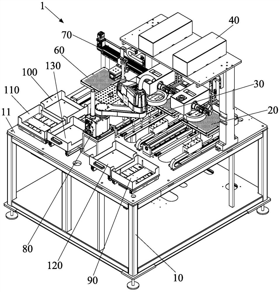
  • Laser code marking and scanning equipment
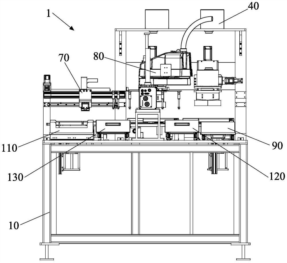
  • Laser code marking and scanning equipment
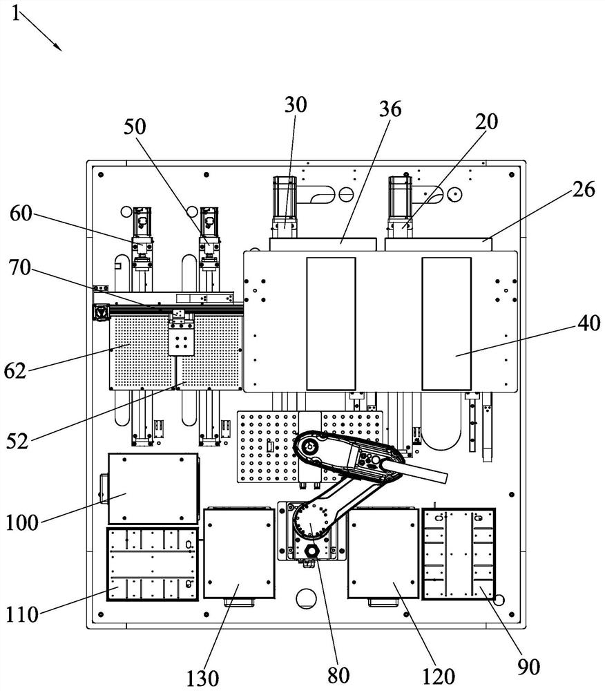
  • Laser code marking and scanning equipment

Examples


Embodiment Construction

[0069] In order to further explain the technical solution of the present invention, the present invention will be described in detail below through specific examples.

[0070] In describing the present invention, it should be understood that the terms "center", "longitudinal", "transverse", "length", "width", "thickness", "upper", "lower", "front", " Back", "Left", "Right", "Vertical", "Horizontal", "Top", "Bottom", "Inner", "Outer", "Clockwise", "Counterclockwise", "X", " The orientation or positional relationship indicated by Y", "Z", etc. is based on the orientation or positional relationship shown in the drawings, and is only for the convenience of describing the present invention and simplifying the description, rather than indicating or implying that the referred device or element must have a specific orientation, are constructed and operate in a particular orientation and therefore are not to be construed as limiting the invention.

[0071] In addition, the terms "firs...


PUM


Abstract

The invention discloses laser code marking and scanning equipment. The laser code marking and scanning equipment comprises a machine frame, a code marking platform mechanism, a laser code marking mechanism, a code scanning platform mechanism, a code scanning mechanism, a material moving mechanism, a product feeding mechanism and a product receiving frame. The code marking platform mechanism, the code scanning platform mechanism, the material moving mechanism, the product feeding mechanism and the product receiving frame are integrated on the same machine frame to form the laser code marking and scanning equipment, and the laser code marking and scanning equipment has the functions of automatic feeding, laser code marking, code scanning and automatic material receiving at the same time. Compared with single laser code marking equipment and single code scanning equipment, the laser code marking and scanning equipment has the advantages that one code scanning process, one set of code scanning equipment and operators are reduced, the equipment and labor cost can be greatly reduced, and the processing efficiency can be improved.

Description

technical field [0001] The invention relates to the technical field of laser processing, in particular to a laser marking and scanning equipment. Background technique [0002] With the development of laser technology, more and more industries adopt laser marking instead of other marking methods such as inkjet coding, such as circuit boards, mobile phones and other consumer electronics industries. At present, most of the laser processing products on the market are used by a single machine. The functions of laser coding, laser scanning into the database and rejecting unqualified products are only independent functions, with low efficiency and high energy consumption. They do not integrate functions and occupy a large area. The data display is not concentrated, there are many operating stations, it is inconvenient to use, and the labor cost and equipment cost are high, thereby reducing the performance of the production equipment. Contents of the invention [0003] The object...

Claims


Application Information

Patent Timeline
IPC IPC(8): B23K26/362B23K26/70
CPCB23K26/362B23K26/70B23K26/702
Inventor 李毅峰续振林李相霖江惠荣陈妙芳黄冬荣
Owner 厦门柔性电子研究院有限公司
Learn More