
Tubular product cutting and transferring device

A transmission device and pipe material technology, applied in the field of mechanical processing, can solve problems such as waste of manpower

Inactive Publication Date: 2021-03-26
张家港台达机械制造有限公司
View PDF10 Cites 3 Cited by
  • Summary
  • Abstract
  • Description
  • Claims
  • Application Information

AI Technical Summary

Problems solved by technology

[0003] The purpose of the embodiments of the present invention is to provide a pipe cutting and conveying device, aiming to solve the problem of wasting manpower

Method used


Image

  • Tubular product cutting and transferring device
  • Tubular product cutting and transferring device
  • Tubular product cutting and transferring device

Examples


Embodiment Construction

[0018] In order to make the object, technical solution and advantages of the present invention clearer, the present invention will be further described in detail below in conjunction with the accompanying drawings and embodiments. It should be understood that the specific embodiments described here are only used to explain the present invention, not to limit the present invention.

[0019] The specific implementation of the present invention will be described in detail below in conjunction with specific embodiments.

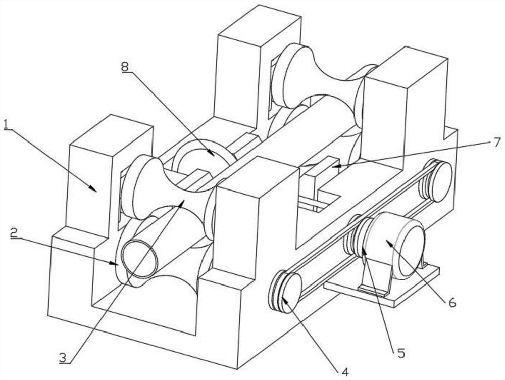
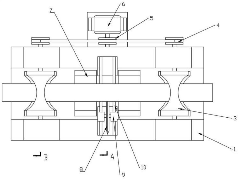
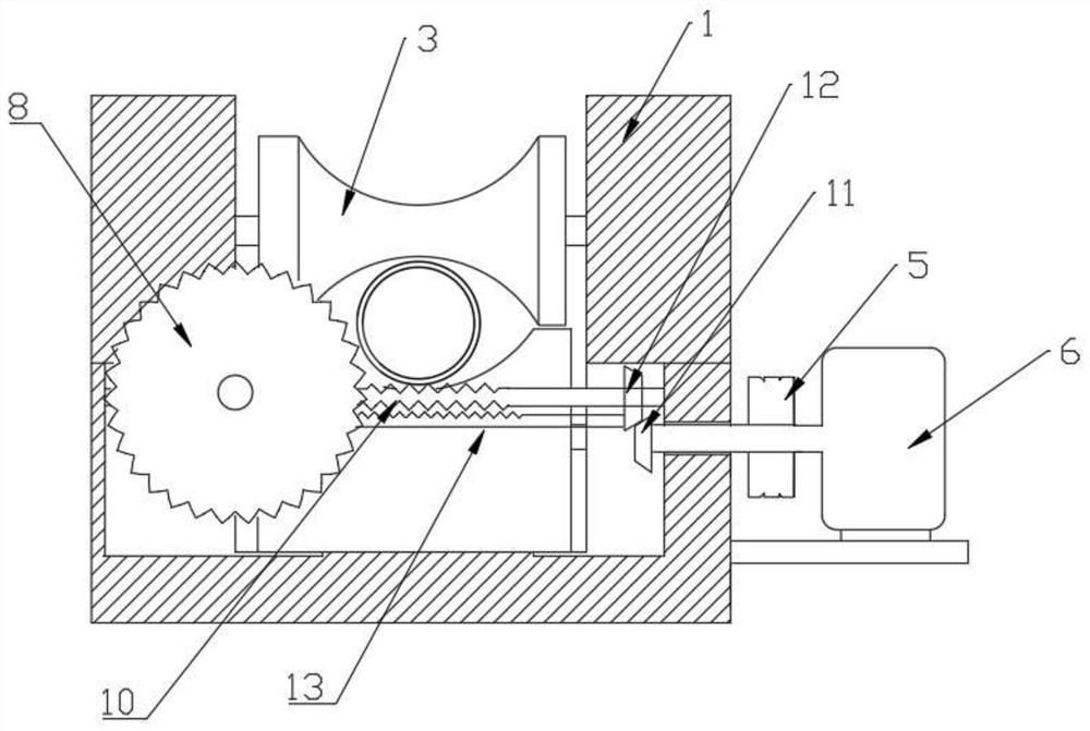
[0020] Such as Figure 1-5 As shown, it is a structural diagram of a pipe cutting and conveying device provided by an embodiment of the present invention, including: a workbench 1 for support and installation;

[0021] The supporting conveying roller 2 is rotated at both ends of the workbench 1 arranged in the conveying direction of the pipe, and is used for supporting and conveying the pipe;

[0022] Press down the conveying roller 3, which can be lifted and r...


PUM


Abstract

The invention is suitable for the technical field of machining and provides a tubular product cutting and transferring device. The tubular product cutting and transferring device comprises a worktable, supporting transfer rollers, pushing transfer rollers, double spiral chute rods, a sawing plate, and a rotary driving part, wherein the supporting transfer rollers are rotatably arranged at two endsof the worktable in a transfer direction of a tubular product for supporting and transferring the tubular product; the pushing transfer rollers are liftably and rotatably connected to two ends of theworktable and are matched with the supporting transfer rollers to clamp and transfer the tubular product; the two double spiral chute rods are rotatably connected to the middle of the worktable and sliding blocks are embedded onto the double spiral chute rods in a fit manner; the sawing plate is rotatably connected to the sliding block and is coaxially and fixedly connected to a connecting gear;the rotary driving part is mounted on the worktable, and an output shaft of the rotary driving part is coaxially connected to a driving one-way belt wheel and a driven gear; the supporting transfer rollers are coaxially and fixedly connected to a driven belt wheel, the double spiral chute rods are coaxially and fixedly connected to a one-way gear, and an insection rack is engaged with the connecting gear. The tubular product cutting and transferring device has the advantages of simple structure, convenience in operation, low production cost, good synchronism and high cutting efficiency.

Description

technical field [0001] The invention belongs to the technical field of mechanical processing, and in particular relates to a pipe material cutting and conveying device. Background technique [0002] With the development of society, the advancement of science and technology, and the development of heavy industry, the further accelerated development of society has improved people's lives. Among them, it is necessary to have high efficiency in the existence of round tubular parts in the machining process, such as: plastic pipes, copper pipes, stainless steel pipes, alloy pipes, etc. Pipes refer to the materials used to make pipe fittings, which are semi-finished parts that have been preliminarily formed. In the pipe processing production line, the length of the pipe is longer when it is produced. It is very inconvenient to transport the pipe produced by the pipe production line directly. Usually, most of the pipes used in industry and life are short in size, so the pipes must ...

Claims


Application Information

Patent Timeline
IPC IPC(8): B26D1/15B26D7/06
CPCB26D7/0666B26D1/15
Inventor 严志平
Owner 张家港台达机械制造有限公司
Learn More