
Propeller blade root and connecting structure of propeller blade root and propeller hub

A technology of propeller and propeller root, which is applied in the field of propeller blade root and connection structure between propeller root and propeller hub. Fewer connecting parts and good fixing stability

Active Publication Date: 2021-03-26
AVIC HUIYANG AVIATION PROPELLER
View PDF4 Cites 1 Cited by
  • Summary
  • Abstract
  • Description
  • Claims
  • Application Information

AI Technical Summary

Problems solved by technology

[0002]The existing composite material blade root is composed of a metal blade handle and a composite material wrapped inside and outside the metal blade handle. Since it needs to be connected with the hub, the metal blade handle The structure is relatively complicated and needs to be produced by RTM molding process. In production, composite materials need to be paved in the inner cavity of the metal petiole. The technical requirements for the molded mold are very high. The paving process is complicated and requires a high technical level of the operator, which is time-consuming. Laborious and costly
To install this kind of blade root into the hub, the connection needs more than a dozen parts such as early warning nuts, filler blocks, and petiole jackets. The structure is very complicated, the assembly process is cumbersome, time-consuming and labor-intensive, and the efficiency is low
Due to the large outer diameter of the petiole, the installation space of the propeller hub is large, the propeller hub is bulky and heavy, and the overall weight of the propeller is large and bulky.

Method used


Image

  • Propeller blade root and connecting structure of propeller blade root and propeller hub
  • Propeller blade root and connecting structure of propeller blade root and propeller hub
  • Propeller blade root and connecting structure of propeller blade root and propeller hub

Examples


Embodiment Construction

[0014] The present invention will be further described below in conjunction with the accompanying drawings and specific embodiments.

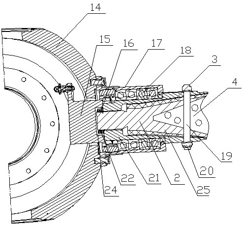
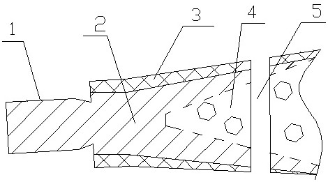
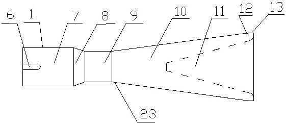
[0015] like figure 1 — Figure 4 As shown, the propeller blade root of this embodiment includes a composite material layer 3 composed of a blade handle 2, a foam core 4, a carbon beam and a skin. The petiole 2 is an integral metal part, and one end of the head is a cylinder 7 with a larger diameter, followed by a round platform 8 with a smaller diameter, followed by a cylinder 9 with the smallest diameter, and then a round platform 10 with a larger diameter. It is a cylinder 13 with the largest diameter, and there is a transitional arc surface 12 between the circular frustum 10 with a larger diameter and the cylinder 13 with the largest diameter. There is an external thread 1 and a keyway 6 at one end on the cylinder 7 with a larger diameter at the head, and a tapered groove 11 is opened in the center of the other end end face. Open the conn...


PUM


Abstract

The invention discloses a propeller blade root and a connecting structure of a propeller blade root and a propeller hub. The head of a blade handle is a cylinder with a larger diameter, a circular truncated cone with a smaller diameter, a cylinder with a smallest diameter, a circular truncated cone with a larger diameter, a transition cambered surface and a cylinder with a largest diameter are sequentially arranged behind the blade handle, the cylinder with the larger diameter is provided with an external thread and a key groove, and a conical groove is formed in the center of the end face ofthe other end of the blade handle; and a connecting through hole is formed in the circular truncated cone with the increased diameter along the radial direction of the blade handle. An accommodating hole for the head of the propeller root is formed in the outer end surface of the stop block in the propeller root mounting hole; a propeller hub inner sleeve and a thrust bearing inner sleeve are pressed and fixed together; the propeller root penetrates through an inner hole of the propeller hub inner sleeve, and the head of the propeller root is locked and fixed to the inner end wall of the propeller hub inner sleeve through a locking piece and a nut I; and a bolt penetrates through the fixing hole of the propeller hub inner sleeve and the bolt connecting hole of the propeller root and is locked and fixed by a nut II. The propeller root is simple in structure, small in diameter, high in strength, simple in connection structure with the propeller hub, fewer in connection parts and high inconnection strength, and the manufactured propeller is small in size, light in weight and high in strength.

Description

technical field [0001] The invention relates to a propeller blade root and a connection structure between the blade root and a hub. Background technique [0002] The existing composite material blade root is composed of a metal petiole and a composite material wrapped inside and outside the metal petiole. Since the metal petiole needs to be connected with the propeller hub, the structure of the metal petiole is relatively complicated, and it needs to be manufactured by RTM molding process. Paving composite materials in the inner cavity of the metal petiole requires very high technical requirements for the forming mold, and the paving process is complicated, requiring high technical level of operators, which is time-consuming, laborious, and costly. Installing the blade root into the hub requires more than a dozen components such as early warning nuts, filler blocks, and petiole jackets. The structure is very complicated, the assembly process is cumbersome, time-consuming and...

Claims


Application Information

Patent Timeline
Patent Type & Authority Applications(China)
IPC IPC(8): B64C27/48B64C27/473
CPCB64C27/48B64C27/473Y02E10/72
Inventor 王慧玲蔡猛姜雪肖田书全
Owner AVIC HUIYANG AVIATION PROPELLER
Learn More