Automatic compression expansion type wastebin

A waste paper and automatic technology, which is applied in the field of trash cans, can solve the problems of occupying a large space and cannot automatically reduce the space occupied by waste paper, so as to achieve the effects of reducing the occupied space, avoiding the waste paper being wet, and increasing the capacity

Active Publication Date: 2021-03-26
宁波甜宝生物信息技术有限公司
View PDF21 Cites 1 Cited by
  • Summary
  • Abstract
  • Description
  • Claims
  • Application Information

AI Technical Summary

Problems solved by technology

[0004] The purpose of the present invention is to solve the disadvantages in the prior art that waste paper is directly discarded in the waste paper bin and will occupy a large amount of space, and the existing waste paper bin cannot automatically reduce the space occupied by waste paper, and proposes an automatic Compression expansion waste paper bin

Method used


Image

  • Automatic compression expansion type wastebin
  • Automatic compression expansion type wastebin
  • Automatic compression expansion type wastebin

Examples


Embodiment 1

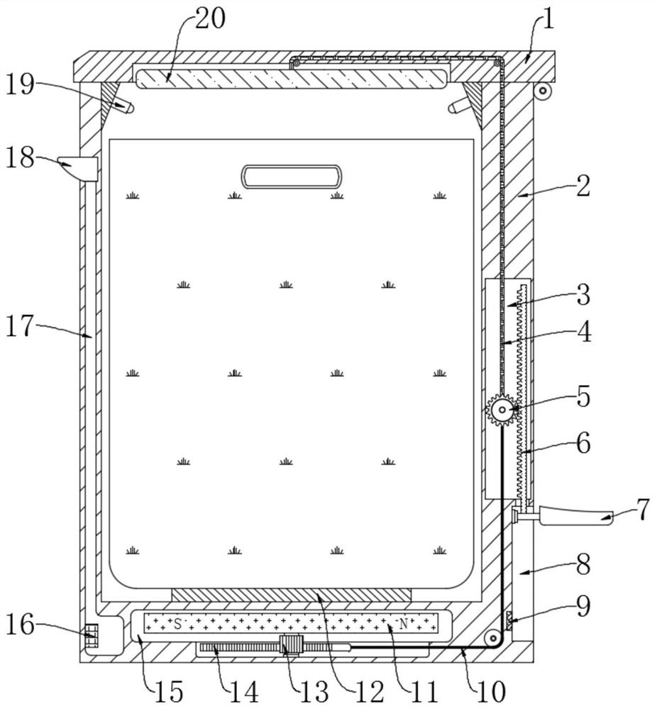
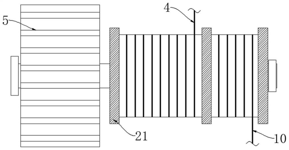
[0023] refer to Figure 1-2 , an automatic compression and expansion type waste paper bin, comprising a lid 1, an inner barrel body and an outer barrel body 2, vertical grooves 3 and liquid storage chambers 17 are symmetrically opened in the side wall of the outer barrel body 2, and the outer barrel body 2 is also provided with There is a liquid replenishment port 18 for replenishing liquid to the liquid storage chamber 17, a circular groove 15 is opened in the bottom wall of the outer barrel body 2, and a chute 8 is opened on the side wall of the outer barrel body 2, and the chute 8 is located in the vertical groove 3, a pedal 7 is slidably installed in the chute 8, and a trigger piece 9 is provided on the groove wall of the chute 8. When the pedal 7 is in contact with the trigger piece 9, the trigger piece 9 sends a specific electric signal, and the vertical groove 3 is installed with the first gear 5 and the first toothed plate 6 meshing with each other, and the lower end o...

Embodiment 2

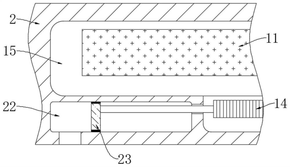
[0035] refer to image 3 The difference between this embodiment and Embodiment 1 is that a negative pressure chamber 22 is provided at the bottom wall of the outer barrel body 2, and a rubber plate 23 is provided for sealing and sliding in the negative pressure chamber 22, and the rubber plate 23 and the second tooth plate 14 A short rod is fixedly connected between them.

[0036]This embodiment can illustrate its functional principle through the following operation mode: when the pedal 7 is stepped on, when the bobbin 21 winds up the second pull cord 10, the second toothed plate 14 will drive the rubber plate 23 to slide to the right, so that the rubber plate Negative pressure is generated on the left side of 23, because the bottom surface of the outer barrel body 2 is flat and directly connected to the ground, so the outside air cannot be replenished in the negative pressure chamber 22, so a negative pressure space will be generated between the outer barrel body 2 and the gr...


PUM


Abstract

The invention discloses an automatic compression expansion type wastebin comprising a bin cover, an inner bin body and an outer bin body. A vertical groove and a liquid storage cavity are symmetrically formed in the side wall of the outer bin body, a circular groove is formed in the bottom wall of the outer bin body, a sliding groove is formed in the side wall of the outer bin body and located below the vertical groove, and a pedal is installed in the sliding groove in a sliding mode. A trigger piece is arranged on the groove wall of the sliding groove, a first gear and a first toothed plate which are meshed with each other are installed in the vertical groove, the lower end of the first toothed plate penetrates through the vertical groove and is fixedly connected with the pedal, the firstgear is fixedly connected with a winding pipe, and a second gear and a second toothed plate which are meshed with each other are installed in the circular groove. A second pull rope is fixedly connected between the second toothed plate and the winding pipe, and a magnetic plate is coaxially supported by the second gear. By means of the automatic compression expansion type wastebin, waste paper inthe wastebin can be automatically compressed and softened, the space occupied by the paper is further reduced, and therefore the capacity of the wastebin is relatively increased.

Description

technical field [0001] The invention relates to the technical field of garbage cans, in particular to an automatic compression and expansion type waste paper can. Background technique [0002] It is inevitable that some waste paper will be produced when the department works, especially the clerical staff, who will come into contact with more waste paper documents, and throwing these waste paper into the plastic waste paper bin will take up a lot of space, thus People need to dump rubbish frequently, causing inconvenience to the staff. [0003] Shredding waste paper can effectively reduce the space occupied by paper, but the existing paper shredders are noisy when used, and the number of paper shredded at a time is limited, the shredding speed is slightly slow, and it takes a long time, and the shredded paper with excellent quality The machine is expensive and needs to be connected to the power supply to use it. Therefore, we propose an automatic compression and expansion wa...

Claims


Application Information

Patent Timeline
Patent Type & Authority Applications(China)
IPC IPC(8): B65F1/14B65F1/16
CPCB65F1/1405B65F1/14B65F1/16B65F2240/156Y02W30/64
Inventor 耿立辉
Owner 宁波甜宝生物信息技术有限公司
Why Eureka
Try Eureka