
Display device, array substrate, thin film transistor and manufacturing method thereof

A technology of thin film transistors and manufacturing methods, applied in the direction of transistors, semiconductor/solid-state device manufacturing, semiconductor devices, etc., can solve the problems of uneven light emission of display panels, threshold voltage drift, etc., to prevent negative threshold voltage drift and length reduction Effect

Pending Publication Date: 2021-07-20
BOE TECH GRP CO LTD +1
View PDF8 Cites 1 Cited by
  • Summary
  • Abstract
  • Description
  • Claims
  • Application Information

AI Technical Summary

Problems solved by technology

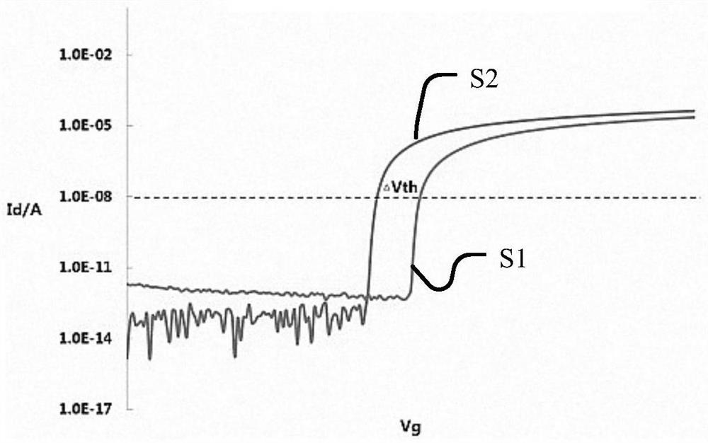
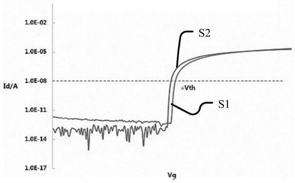
However, after the thin film transistors are manufactured, the display panel needs to continue with other follow-up processes, and some of the high-temperature processes will cause the threshold voltage drift of the thin film transistors, which will easily cause problems such as uneven light emission of the display panel, especially for OLEDs. (Organic Light-Emitting Diode, Organic Light-Emitting Diode) display panel, the problem of threshold voltage drift is particularly serious

Method used


Image

  • Display device, array substrate, thin film transistor and manufacturing method thereof
  • Display device, array substrate, thin film transistor and manufacturing method thereof
  • Display device, array substrate, thin film transistor and manufacturing method thereof

Examples


Embodiment Construction

[0059]Example embodiments will now be described more fully with reference to the accompanying drawings. Example embodiments may, however, be embodied in many forms and should not be construed as limited to the embodiments set forth herein; rather, these embodiments are provided so that this disclosure will be thorough and complete, and will fully convey the concept of example embodiments to those skilled in the art. The same reference numerals in the drawings denote the same or similar structures, and thus their detailed descriptions will be omitted. Furthermore, the drawings are merely schematic illustrations of the present disclosure and are not necessarily drawn to scale.

[0060] Although relative terms such as "upper" and "lower" are used in this specification to describe the relative relationship of one component of an icon to another component, these terms are used in this specification only for convenience, for example, according to the description in the accompanying...


PUM

PropertyMeasurementUnit
widthaaaaaaaaaa

Abstract

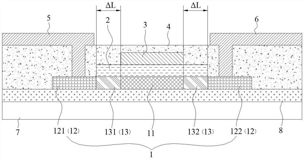
The invention relates to a display device, an array substrate, a thin film transistor and a manufacturing method thereof, and relates to the technical field of display. The thin film transistor comprises an active layer, a gate insulating layer, a gate electrode, a dielectric layer, a source electrode and a drain electrode. The active layer is provided with a channel region, doped regions located on the two sides of the channel region and buffer regions separated between the doped regions and the channel region, and the doping concentration of the buffer regions is smaller than that of the doped regions. The gate insulating layer is arranged on one side of the active layer, covers the channel region and the buffer region, and exposes the doped region. The grid electrode is arranged on the surface, away from the active layer, of the grid insulating layer, and the projection of the grid electrode on the active layer coincides with the channel region. The dielectric layer covers the grid electrode, the grid insulating layer and the active layer; the source electrode and the drain electrode are arranged on the surface, away from the active layer, of the dielectric layer, located on the two sides of the channel region and connected to the different doped regions.

Description

technical field [0001] The present disclosure relates to the field of display technology, in particular, to a display device, an array substrate, a thin film transistor and a method for manufacturing the thin film transistor. Background technique [0002] In a display panel, a thin-film transistor (TFT) is an important circuit device for driving pixels to emit light. Existing thin-film transistors are generally divided into two types: bottom-gate structure (bottom-gate) and top-gate structure (top-gate). The gate structure is widely used. However, after the thin film transistors are manufactured, the display panel needs to continue with other follow-up processes, and some of the high-temperature processes will cause the threshold voltage drift of the thin film transistors, which will easily cause problems such as uneven light emission of the display panel, especially for OLEDs. For Organic Light-Emitting Diode (Organic Light-Emitting Diode) display panels, the problem of th...

Claims


Application Information

Patent Timeline
Patent Type & Authority Applications(China)
IPC IPC(8): H01L29/786H01L29/06H01L29/423H01L21/34H01L27/12H01L27/32G02F1/1362G02F1/1368
CPCH01L29/7869H01L29/0684H01L29/42384H01L29/66969H01L27/1222H01L27/1225G02F1/1362G02F1/1368H01L21/34H01L29/66477H01L29/78621H01L27/127H01L27/1288H01L29/0607H01L29/401H01L29/41733H01L29/66742H01L29/78696
Inventor 贵炳强刘珂黄鹏高涛
Owner BOE TECH GRP CO LTD
Learn More