Quasi-zero stiffness vibration isolation platform suitable for ultralow-frequency vibration isolation
A vibration isolation platform, quasi-zero stiffness technology, applied in low internal friction springs, vibration suppression adjustment, spring/shock absorber functional characteristics, etc., can solve problems such as unsatisfactory vibration isolation effect, and achieve simple and convenient assembly and low cost , the effect of saving money
- Summary
- Abstract
- Description
- Claims
- Application Information
AI Technical Summary
Problems solved by technology
Method used
Image
Examples
specific Embodiment approach 1
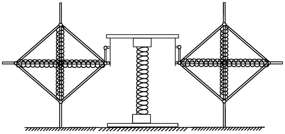
[0038] Specific implementation mode one: combine figure 1 Describe this embodiment. The quasi-zero stiffness vibration isolation platform suitable for ultra-low frequency vibration isolation described in this embodiment includes two link spring assemblies and a central vibration isolation platform assembly. The two link spring assemblies They are respectively arranged on both sides of the central vibration isolation platform assembly, and each of the link spring assemblies is rotatably connected with the central vibration isolation platform assembly.
[0039] The invention utilizes the nonlinear change of the system's own stiffness to realize that the dynamic stiffness of the system is close to zero during the vibration process, thereby achieving the purpose of ultra-low frequency vibration isolation.
[0040] The design idea of this vibration isolation platform is clear, and the structural design is relatively simple, the cost is relatively cheap, and it can also play a tar...
specific Embodiment approach 2
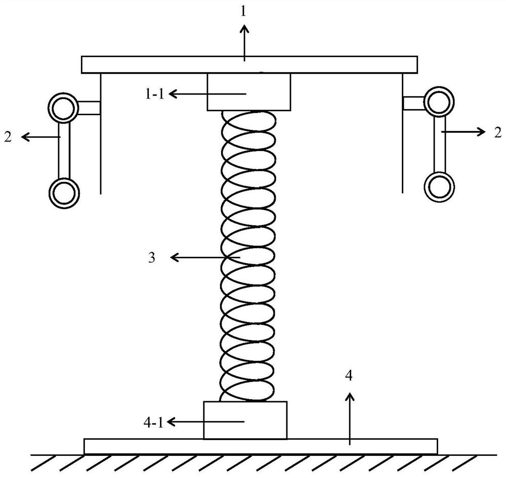
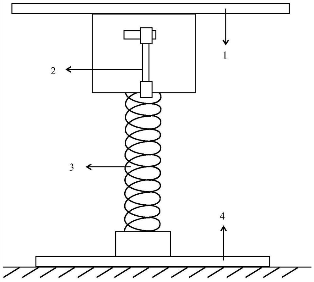
[0041] Specific implementation mode two: combination Figure 2 to Figure 6 Describe this embodiment, the central vibration isolation platform assembly described in this embodiment includes a loading platform 1, two platform connecting rods 2, load-bearing springs 3 and a grounding platform 4,
[0042] The loading platform 1 and the grounding platform 4 are arranged horizontally from top to bottom, the upper end of the load-bearing spring 3 is connected to the lower surface of the loading platform 1, the lower end of the load-bearing spring 3 is connected to the upper surface of the grounding platform 4, and the connecting rods of the two platforms 2 are symmetrically arranged on both sides of the loading platform 1, and the upper end of the platform connecting rod 2 is rotationally connected with the loading platform 1, and the lower end of the platform connecting rod 2 is connected with the connecting rod spring assembly.
[0043] Other components and connections are the same...
specific Embodiment approach 3
[0044] Specific implementation mode three: combination figure 2 and image 3 To illustrate this embodiment, the middle part of the lower surface of the loading platform 1 in this embodiment is provided with a first threaded cap 1-1, and the upper end of the load-bearing spring 3 is connected to the first threaded cap 1-1.
[0045] Other components are the same as those in the second embodiment in terms of connections.
PUM
 Abstract
Description
Claims
Application Information
 - R&D
- Intellectual Property
- Life Sciences
- Materials
- Tech Scout
- Unparalleled Data Quality
- Higher Quality Content
- 60% Fewer Hallucinations
Browse by: Latest US Patents, China's latest patents, Technical Efficacy Thesaurus, Application Domain, Technology Topic, Popular Technical Reports.
© 2025 PatSnap. All rights reserved.Legal|Privacy policy|Modern Slavery Act Transparency Statement|Sitemap|About US| Contact US: help@patsnap.com


