
Network security monitoring equipment with anti-damage function

A technology for network security and monitoring equipment, applied in the direction of mechanical equipment, engine frame, color TV components, etc., can solve the problems of reduced life, inconvenient use, damage to monitoring equipment, etc., and achieve large installation and disassembly functions, convenient Installation and removal, the effect of improving the convenience

Inactive Publication Date: 2021-03-26
湖南云能信息科技有限公司
View PDF0 Cites 0 Cited by
  • Summary
  • Abstract
  • Description
  • Claims
  • Application Information

AI Technical Summary

Problems solved by technology

[0005] Aiming at the deficiencies of the prior art, the present invention provides a network security monitoring device with an anti-sabotage function, which solves the problem that most of the existing network security monitoring devices on the market have some simple conditions of use. The monitoring equipment is in the open air. As the use time continues to increase, the external weather changes constantly, which will cause unnecessary damage to the monitoring equipment. It is very inconvenient to use. At the same time, the entire monitoring equipment cannot For protection, the entire monitoring equipment does not have the function of anti-damage, and its service life is reduced, which is a troublesome problem in application

Method used


Image

  • Network security monitoring equipment with anti-damage function
  • Network security monitoring equipment with anti-damage function
  • Network security monitoring equipment with anti-damage function

Examples


Embodiment Construction

[0021] The following will clearly and completely describe the technical solutions in the embodiments of the present invention with reference to the accompanying drawings in the embodiments of the present invention. Obviously, the described embodiments are only some, not all, embodiments of the present invention. Based on the embodiments of the present invention, all other embodiments obtained by persons of ordinary skill in the art without making creative efforts belong to the protection scope of the present invention.

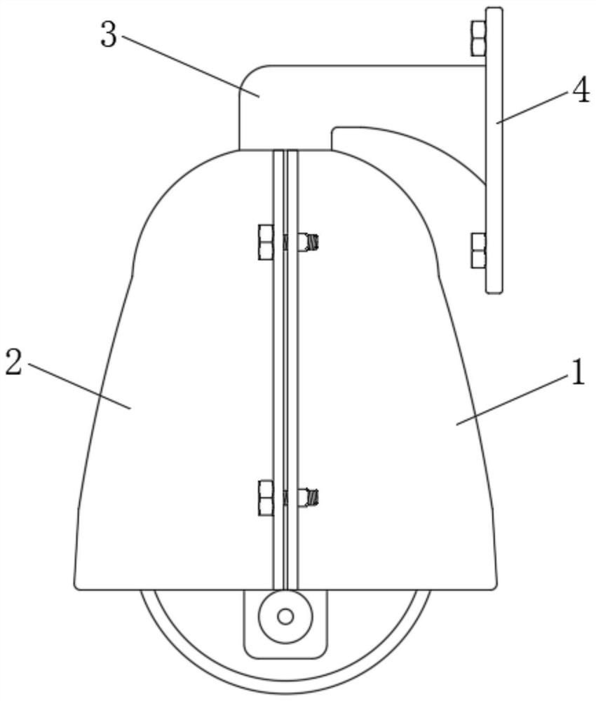
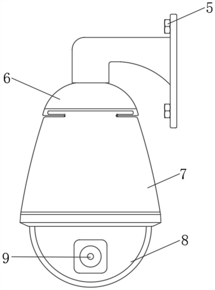
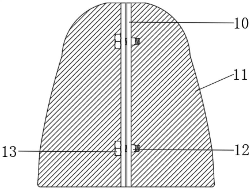
[0022] see Figure 1-4 , the embodiment of the present invention provides a technical solution: a network security monitoring device with an anti-sabotage function, including a device main body 7, a support rod 3, a rotation auxiliary mechanism 6 and a camera device 8, and the exterior of the device main body 7 is respectively A front protective cover 1 and a rear protective cover 2 are provided, and the outer sides of the front protective cover 1 and the rear...


PUM


Abstract

The invention discloses network security monitoring equipment with an anti-damage function. The network security monitoring equipment comprises a device main body, a supporting rod, a rotation assisting mechanism and a camera device, wherein a front protective cover and a rear protective cover are separately arranged on the outside of the device main body; and connecting plates are fixedly arranged on the outer sides of the front protective cover and the rear protective cover in a bonding manner. The network security monitoring equipment is provided with the front protective cover and the rearprotective cover, and the front protective cover and the rear protective cover on the two ends are connected for protection through the connection between second fixing screws and bolts. Therefore, monitoring equipment of different sizes can be protected and used, and the diversity of using ways is achieved. Meanwhile, buffering, balance keeping and shock absorption effects can be achieved through buffer pads bonded internally. Moreover, the buffer pads are also capable of protecting the device main body and well solving the problem that the equipment is damaged in the event of an impact. Theflexibility during use is greatly improved. The application is relatively convenient. The mounting and dismounting are convenient.

Description

technical field [0001] The invention relates to the technical field of monitoring equipment, in particular to a network security monitoring equipment with an anti-destructive function. Background technique [0002] The camera part is the front part of the monitoring system and the "eyes" of the whole system. It is arranged at a certain position of the monitored place, so that its field of view can cover all parts of the entire monitored place. [0003] Most of the network security monitoring equipment currently on the market has some simple conditions of use. The monitoring equipment is in the open state during use. As the use time continues to increase, the external weather changes constantly, which will bring inconvenience to the monitoring equipment Necessary damage is very inconvenient to use. At the same time, the entire monitoring equipment cannot be protected when it encounters an impact. The entire monitoring equipment does not have the anti-damage function, and its...

Claims


Application Information

Patent Timeline
IPC IPC(8): F16M11/04F16M11/08F16M7/00F16M13/02F16F15/02H04N5/225H04N7/18
CPCF16M11/04F16M11/08F16M7/00F16M13/02F16F15/02H04N7/18H04N23/50H04N23/51
Inventor 张雯宇
Owner 湖南云能信息科技有限公司
Learn More