
Heat pump dehumidification device and method for underground hot spring area of abandoned mine

A technology of heat pump dehumidification and hot springs, applied in heating methods, safety devices, ventilation of mines/tunnels, etc., can solve problems such as large energy loss, increased operating costs, and no energy recovery and utilization, so as to reduce operating costs and have strong adaptability , the effect of reducing energy waste

Pending Publication Date: 2021-03-26
河北寰球工程有限公司
View PDF0 Cites 0 Cited by
  • Summary
  • Abstract
  • Description
  • Claims
  • Application Information

AI Technical Summary

Problems solved by technology

One is to use the original mine ventilation system to ventilate and dehumidify. This system is only suitable for the situation where the moisture content of the outdoor air is less than that of the underground hot spring area. It is generally suitable for winter operation, and the summer operation is restricted. If the water content is greater than the moisture content of the underground hot spring area, the humidity in the hot spring area cannot be removed, which does not meet the design requirements for the humidity of the hot spring area, and is not suitable for year-round operation.
Another type of dehumidification system is to add a dehumidification unit to the mine ventilation system. The dehumidification system can meet the humidity requirements of the underground hot spring area in summer and meet the operating conditions throughout the year. However, the air supply and exhaust are all DC systems, and the energy is not recovered. Utilization, the energy loss is huge, the operating cost increases, and it does not comply with the energy-saving policy

Method used


Image

  • Heat pump dehumidification device and method for underground hot spring area of abandoned mine

Examples


Embodiment 1

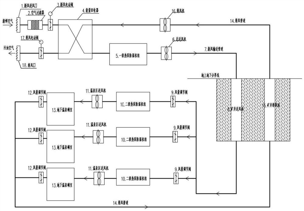
[0027] This embodiment provides a heat pump dehumidification device for an underground hot spring area in an abandoned mine. see figure 1 As shown, the heat pump dehumidification device in the underground hot spring area of ​​the abandoned mine in this embodiment includes:

[0028] The fresh air inlet 1, the air filter 2, the fresh air electric valve 3, the primary heat pump dehumidification unit 5, the total blower 6, the mine air supply duct 8 and the work area connected in sequence by the fresh air conveying pipeline 7, and in the work area The mine exhaust duct 15, the exhaust fan 16, the exhaust electric valve 17 and the exhaust outlet 18 are sequentially connected through the exhaust duct 14;

[0029] Wherein, the working area is three groups of parallel working units, and each group of working units includes an air volume regulating valve 9, a secondary heat pump dehumidification unit 10, a blower 11 in the hot spring area, an underground hot spring chamber 13 and an a...

Embodiment 2

[0034] This embodiment provides a heat pump dehumidification method in an underground hot spring area of ​​an abandoned mine, which is carried out using the device in Embodiment 1. see figure 1 As shown, the heat pump dehumidification method of the underground hot spring area of ​​the abandoned mine in this embodiment includes:

[0035] Turn on the fresh air electric valve 3, the exhaust electric valve 17 and other equipment power supplies, so that fresh air enters the air filter 2 from the fresh air inlet 1 through the fresh air delivery pipe 7, and the air filter 2 is used to filter impurities and dust in the fresh air , so that the fresh air entering the device is guaranteed to have a certain degree of cleanliness; then the energy is recovered through the energy recovery device 4, which is essentially an air heat exchanger for exchanging the cold and heat in the fresh air and exhaust air Then send it to the first-level heat pump dehumidification unit 5 for processing. The ...

Embodiment 3

[0037] This embodiment provides a heat pump dehumidification method in the underground hot spring area of ​​an abandoned mine in winter, using the device in Embodiment 1. see figure 1 As shown, the heat pump dehumidification method of the underground hot spring area of ​​the abandoned mine in this embodiment includes:

[0038] In winter, the moisture content of the outdoor air is less than the moisture content of the underground hot spring area, the air is relatively dry and the temperature is relatively low. At this time, the fresh air enters the air filter 2 from the fresh air inlet 1 through the fresh air conveying pipe 7 for filtering, and enters after filtering. The energy recovery device 4 recovers the energy, and then sends it to the primary heat pump dehumidification unit 5 for heat treatment in its heat pump mode, and then sends it to the mine air supply channel 8 through the main blower 6 and finally transports it to the underground working area. The working area is...


PUM


Abstract

The invention discloses a heat pump dehumidification device and method for an underground hot spring area of an abandoned mine. The device comprises a fresh air inlet, an air filter, a first-stage heat pump dehumidification unit, a main air feeder, a mine air supply duct and a working area which are sequentially connected through a fresh air conveying pipeline. A mine exhaust duct, an exhaust fanand an exhaust outlet which are sequentially connected through an exhaust pipeline in the follow-up process of the working area are further included. The working area comprises a plurality of groups of working units which are connected in parallel, and each group of working unit comprises a two-stage heat pump dehumidification unit, a hot spring area air feeder and an underground hot spring chamber which are connected in sequence. And energy recoverers are further arranged on the fresh air conveying pipeline between the air filter and the first-stage heat pump dehumidification unit and the exhaust pipeline between the exhaust fan and the exhaust outlet. The energy recoverers and the two-stage heat pump dehumidification units are mainly arranged, the defects in the prior art are overcome, and the popularization value is high.

Description

technical field [0001] The invention relates to a heat pump dehumidification device and method for an underground hot spring area of ​​an abandoned mine, belonging to the technical field of air conditioning. Background technique [0002] Under the background of the construction of "ecological civilization", the construction of green mines and the reduction of environmental pollution have achieved good economic, environmental and social benefits. In the process of implementing the transformation of the mining industry, it has become an innovation to combine the treatment of abandoned mines with the development of underground hot spring tourism. [0003] In the process of building hot springs underground in abandoned mines, a very important project is the design of the ventilation and dehumidification system. At present, there are two commonly used dehumidification schemes. One is to use the original mine ventilation system to ventilate and dehumidify. This system is only sui...

Claims


Application Information

Patent Timeline
Patent Type & Authority Applications(China)
IPC IPC(8): F24F7/003F24F7/08F24F8/10F24F12/00F24F3/14F24F11/89E21F1/00E21F3/00E21F5/00
CPCE21F1/00E21F3/00E21F5/00F24F3/1405F24F7/08F24F12/001F24F11/89
Inventor 王金山张燕飞宋华禹孝飞刘哲丹师利楠赵小燕唐岩王晓亮李莉
Owner 河北寰球工程有限公司
Learn More