Optical fiber spectrometer and implementation method

A fiber optic spectrometer and grating technology, which is applied in the field of fiber optic spectrometers, can solve problems such as weakening of structural strength, grating seat easy to be subjected to force off-axis, and deformation of the spectrometer shell, so as to achieve strong resistance to external forces or temperature effects, and to isolate accidental interference , Reliable effect of thickness and strength

Pending Publication Date: 2021-03-26
合肥立睿光电科技有限公司 +1
View PDF7 Cites 0 Cited by
  • Summary
  • Abstract
  • Description
  • Claims
  • Application Information

AI Technical Summary

Problems solved by technology

[0003] The traditional method is to use screws and glue to adjust and fix the optical components. The adjustment accuracy is small, the operation is difficult, and the stability is poor. For the grating in the fiber optic spectrometer, the grating is first installed on the grating holder, and then passes through the two holes at the bottom of the grating holder. Adjust the angle of the grating with two screws and fix it. This method will easily cause the grating seat to tilt, causing the direction of the grating line to be not perpendicular to the plane of the optical path. The sink head of the groove causes the structural strength to weaken, and the spectrometer shell is easily deformed by temperature or external force;
[0004] Another major disadvantage of installing the grating base on the bottom is that it is necessary to use a screwdriver to hold and rotate the grating base from the bottom surface for debugging, which is not only inconvenient for debugging, but also makes the grating base easy to be biased by force, and the fastened grating fixing screws are exposed outside the shell , is prone to the problem of accidental touch, so we propose a fiber optic spectrometer and its implementation method

Method used


Image

  • Optical fiber spectrometer and implementation method
  • Optical fiber spectrometer and implementation method
  • Optical fiber spectrometer and implementation method

Examples


Embodiment Construction

[0023] The following will clearly and completely describe the technical solutions in the embodiments of the present invention with reference to the accompanying drawings in the embodiments of the present invention. Obviously, the described embodiments are only some, not all, embodiments of the present invention. Based on the embodiments of the present invention, all other embodiments obtained by persons of ordinary skill in the art without making creative efforts belong to the protection scope of the present invention.

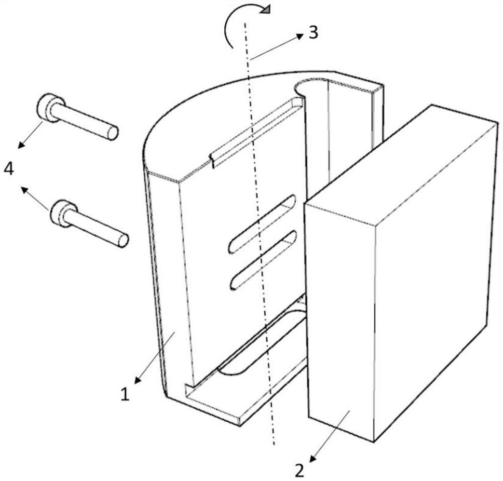
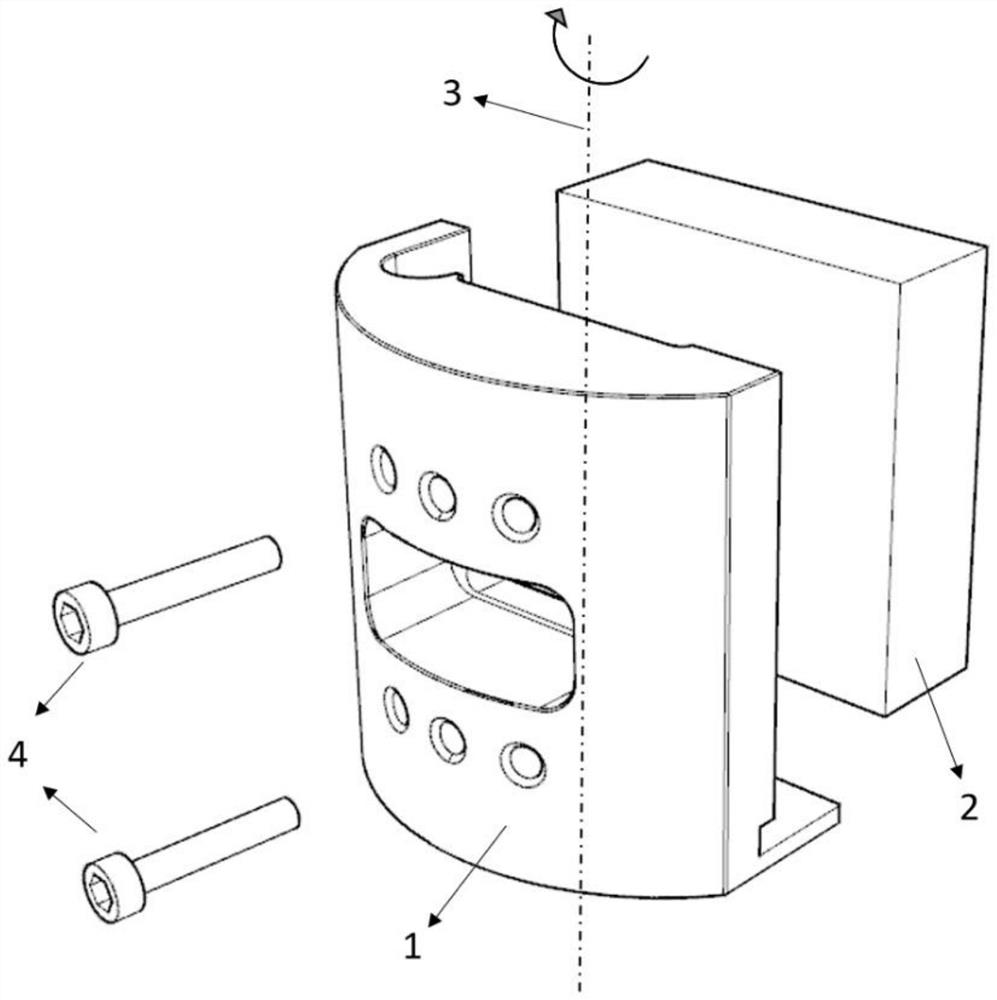
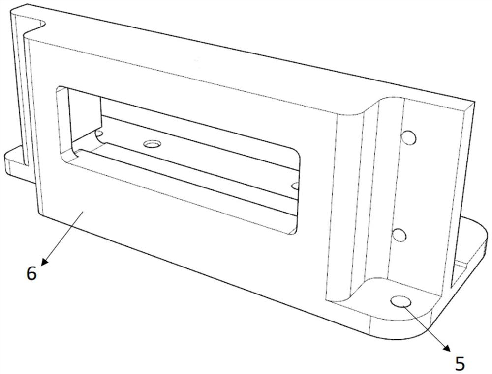
[0024] see Figure 1 to Figure 5 , the present invention provides a technical solution: a fiber optic spectrometer, including a grating seat 1 and a detector seat 6, a grating 2 is provided on one side of the grating seat 1, and six adjustment holes are symmetrically opened inside the grating seat 1, and the grating The surface of 2 is provided with six screw slots corresponding to the adjustment holes, and the grating base 1 and the grating 2 are fixed by adj...


PUM


Abstract

The invention discloses an optical fiber spectrometer which comprises a grating base and a detector base, a grating is arranged at one side of the grating base, six adjusting holes are symmetrically formed in the grating base, six screw grooves corresponding to the adjusting holes are formed in the surface of the grating, and adjusting fixing screws penetrate through the adjusting holes to extendinto the screw grooves to fix the grating base and the grating. A rotating shaft is arranged in the upper portion of the middle position of the grating base and the grating, a square groove is formedin the detector base, a detector is installed in the square groove, a PCB is installed on the surface of the detector, threaded holes are formed in the four corners of the PCB, threaded grooves used in cooperation with the threaded holes are formed in the surface of the detector base, and a mounting seat is arranged at one end part of the detector seat. The side wall of the grating is designed tobe installed, and the adjusting screw and the fixing screw are both perpendicular to the rotating shaft on the side face, so that the grating cannot deviate from the shaft during fixing or rotating debugging, the wall thickness of the side wall is uniform, and reliable thickness strength can be guaranteed.

Description

technical field [0001] The invention belongs to the technical field of optical fiber spectrometer, and in particular relates to an optical fiber spectrometer and a realization method. Background technique [0002] The fiber optic spectrometer can perform spectral analysis on the polychromatic optical signal input by the optical fiber, and obtain the intensity of light of different wavelengths. The fiber optic spectrometer is small in size and easy to use. It can be integrated in the system as a core module to realize the function of spectral analysis and has broad application prospects. The structure of the fiber optic spectrometer generally includes: fiber seat, entrance slit, aperture, concave mirror , grating, CCD detector, etc. Spectral resolution and sensitivity are key indicators of spectrometer performance, and both are closely related to the position and angle of each optical element. The installation and fixing methods of each optical element need to have good adj...

Claims


Application Information

Patent Timeline
Patent Type & Authority Applications(China)
IPC IPC(8): G01J3/28G01J3/18G01J3/02
CPCG01J3/28G01J3/18G01J3/0202G01J3/0218
Inventor 王宏
Owner 合肥立睿光电科技有限公司
Why Eureka
Try Eureka