Ultrasonic-assisted unmanned aerial vehicle autonomous stable landing system and method

An unmanned aerial vehicle and ultrasonic technology, applied in the field of unmanned aerial vehicles, can solve the problems of difficult speed control, inability to achieve autonomous landing of unmanned aerial vehicles, insufficient positioning accuracy, etc., to achieve high flexibility and reduce the risk of damage to unmanned aerial vehicles , the effect of high positioning accuracy

Pending Publication Date: 2021-03-26
TONGJI UNIV
View PDF8 Cites 3 Cited by
  • Summary
  • Abstract
  • Description
  • Claims
  • Application Information

AI Technical Summary

Problems solved by technology

However, when the control method and system disclosed in this patent are actually used, only when the landing position is a landing platform, can the precise positioning and landing of the UAV be guaranteed, and the scope of application is small, and it is impossible to realize the autonomous landing of the UAV at any landing point; through The method of detecting the vertical reverse acceleration to judge whether the UAV touches the ground is prone to misjudgment, and the RTK positioning method has insufficient positioning accuracy in the vertical direction, and it is difficult to perform real-time speed control during the landing process to ensure the stability of the UAV. landing

Method used


Image

  • Ultrasonic-assisted unmanned aerial vehicle autonomous stable landing system and method
  • Ultrasonic-assisted unmanned aerial vehicle autonomous stable landing system and method
  • Ultrasonic-assisted unmanned aerial vehicle autonomous stable landing system and method

Examples


Embodiment 1

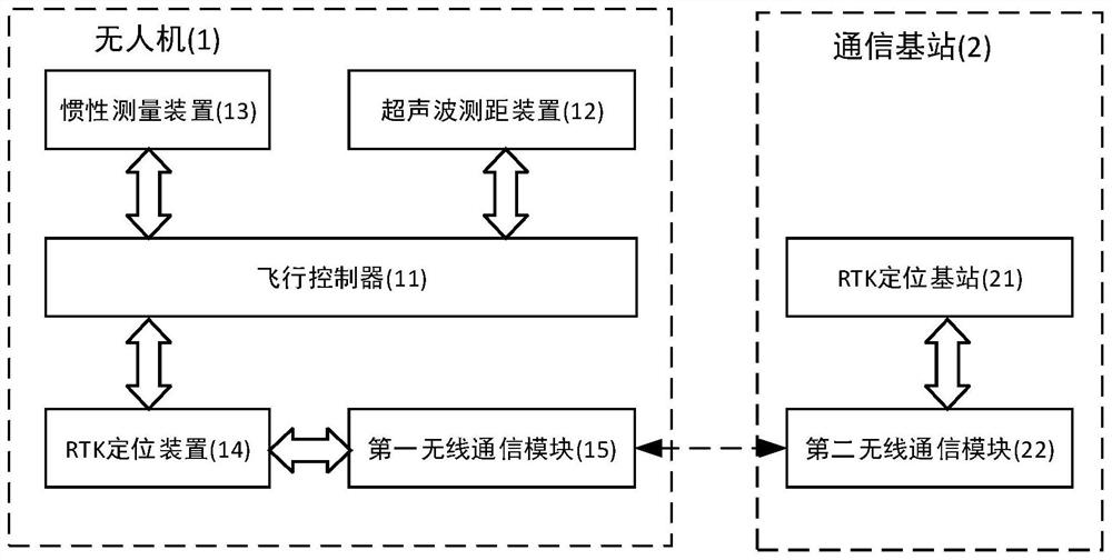
[0044] An ultrasonic-assisted UAV autonomous stable landing system, the overall structure is as follows: figure 1 As shown, it includes a UAV 1 and a communication base station 2. The UAV 1 is equipped with a flight controller 11, an ultrasonic distance measuring device 12, an inertial measurement unit 13 (Inertial measurement unit, IMU), an RTK positioning device 14 (Real- time kinematic) and the first wireless communication module 15; the communication base station 2 includes the RTK positioning base station 21 and the second wireless communication module 22, and the RTK positioning base station 21 is connected with the second wireless communication module 22.

[0045] The flight controller 11 is respectively connected with the ultrasonic ranging device 12 , the inertial measurement device 13 and the RTK positioning device 14 , and the RTK positioning device 14 is connected with the first wireless communication module 15 .

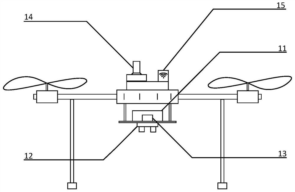
[0046] Such as figure 2As shown, in this embodim...


PUM


Abstract

The invention relates to an ultrasonic-assisted unmanned aerial vehicle autonomous stable landing system and method, the landing system comprises an unmanned aerial vehicle and a communication base station, and a flight controller, an ultrasonic ranging device, an inertial measurement device and an RTK positioning device are carried on the unmanned aerial vehicle; the landing method comprises thefollowing steps that the unmanned aerial vehicle flies to a preset position over a landing point; the unmanned aerial vehicle descends downwards to the preset maximum ground clearance; the ultrasonicranging device measures the ground clearance of the unmanned aerial vehicle and adjusts the landing speed of the unmanned aerial vehicle in real time according to the ground clearance until the unmanned aerial vehicle touches the ground. Compared with the prior art, the system and method have the advantages that positioning marks do not need to be arranged at landing points, accurate positioning in the horizontal direction is achieved in an RTK positioning mode, accurate positioning in the vertical direction is achieved through an ultrasonic ranging device, and accurate landing of the unmannedaerial vehicle is achieved; and the ground clearance of the unmanned aerial vehicle is measured in real time through the ultrasonic ranging device, the landing speed is adjusted in real time accordingly, and accurate control over the landing speed of the unmanned aerial vehicle is achieved.

Description

technical field [0001] The invention relates to the field of unmanned aerial vehicles, in particular to a system and method for an autonomous and stable landing of an unmanned aerial vehicle assisted by ultrasonic waves. Background technique [0002] In recent years, the continuous maturity of technologies such as micro-electromechanical systems, navigation, and software platforms has provided strong conditions for the rapid development of UAV technology. Due to its small size, light weight, low cost, and good mobility, UAVs have been widely used in many industries such as aerial photography, transportation, agricultural plant protection, and security. [0003] As the operating environment of UAVs becomes more and more complex, people put forward higher requirements for its performance in all aspects, and autonomous landing, as an important part of realizing the intelligent operation of UAVs, has attracted extensive attention from researchers. Many current application scena...

Claims


Application Information

Patent Timeline
Patent Type & Authority Applications(China)
IPC IPC(8): G05D1/06G01S15/93
CPCG05D1/0676G01S15/93
Inventor 何斌甘坤李刚陆萍王志鹏周艳敏朱忠攀
Owner TONGJI UNIV
Why Eureka
Try Eureka