Stator core, stator, permanent magnet synchronous motor, compressor and refrigeration equipment

A permanent magnet synchronous motor and stator core technology, applied in the field of compressors, can solve problems such as vibration and noise, and achieve the effects of improving vibration and noise, reducing the difficulty of production technology, and reducing radial electromagnetic force waves

Inactive Publication Date: 2021-03-26
ANHUI MEIZHI PRECISION MFG
View PDF6 Cites 0 Cited by
  • Summary
  • Abstract
  • Description
  • Claims
  • Application Information

AI Technical Summary

Problems solved by technology

[0003] In the related art, in the rotary DC inverter compressor, the motor generally adopts the built-in permanent magnet motor. In the design of the motor with high power density, after the motor is energized, the stator magnetic field interacts with the rotor magnetic field to generate a composite magnetic field, resulting in vibration noise

Method used


Image

  • Stator core, stator, permanent magnet synchronous motor, compressor and refrigeration equipment
  • Stator core, stator, permanent magnet synchronous motor, compressor and refrigeration equipment
  • Stator core, stator, permanent magnet synchronous motor, compressor and refrigeration equipment

Examples


Embodiment 1

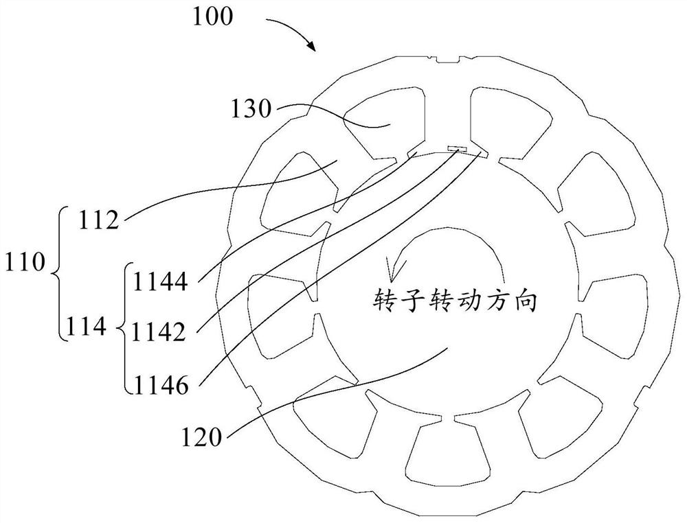
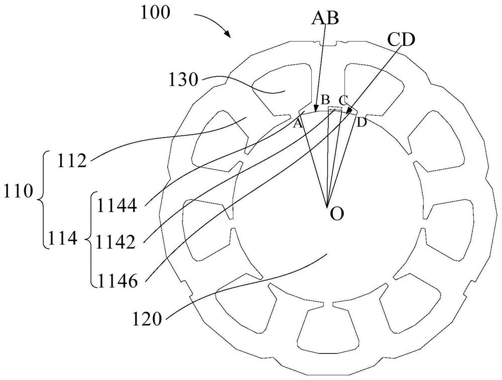
[0075] figure 1 It shows one of the structural schematic diagrams of the stator core according to the embodiment of the present invention, figure 2 Shows the second structural schematic diagram of the stator core according to the embodiment of the present invention, wherein, as figure 1 and figure 2 As shown, the stator core consists of:

[0076] The stator inner hole 120 is used to pass through the rotor; a plurality of stator punches, each stator punch has a thickness, and the plurality of stator punches are stacked along the axial direction of the stator inner hole 120, and the stator punches include a stator yoke and a A plurality of stator teeth 110 distributed in the circumferential direction of the yoke; wherein, a magnetic conduction hole 1142 is opened along the thickness direction of the stator punch.

[0077] In the embodiment of the present invention, the stator core is provided with a stator inner hole 120 , and the rotor of the motor can pass through the sta...

Embodiment 2

[0082] In some embodiments of the present invention, such as figure 2As shown, the stator tooth 110 includes: a tooth root 112 connected with the stator yoke; a tooth crown 114 connected with the end of the tooth root 112 away from the stator yoke; The thickness of at least one tooth crown 114 on at least one stator punching plate is provided with a magnetic conduction hole 1142, along the axial direction of the tooth root, the projection of the magnetic conduction hole 1142 on the tooth crown makes the tooth crown 114 away from the tooth root 112 is divided into a first tooth crown surface 1144 and a second tooth crown surface 1146 , the area of ​​the first tooth crown surface 1144 is smaller than the area of ​​the second tooth crown surface 1146 .

[0083] In the embodiment of the present invention, along the axial direction of the tooth root, the projection of the magnetic conduction hole 1142 on the tooth crown 114 separates the surface of the tooth crown 114 away from th...

Embodiment 3

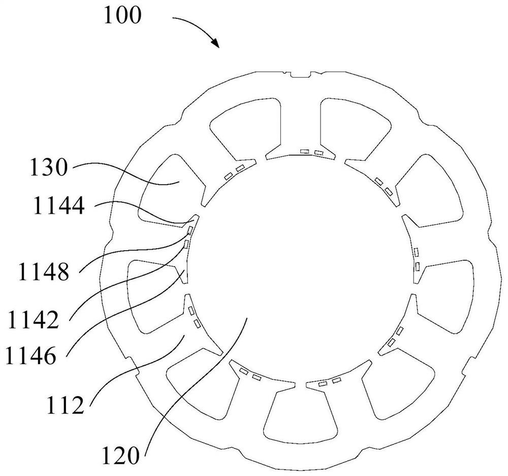
[0088] In some embodiments of the present invention, the number of stator punching pieces is multiple, and the plurality of stator punching pieces include: at least one first stator punching piece 100; at least one second stator punching piece, the first stator punching piece 100 and the second stator punch are stacked along the axial direction of the stator inner hole 120 , and the second stator punch is provided with a magnetic conduction hole 1142 .

[0089] In the embodiment of the present invention, the stator core of the motor includes a plurality of stacked stator punches, wherein the plurality of stator punches include at least one first stator punch 100 and at least one second stator punch. The first stator punching piece 100 and the second stator punching piece are stacked along the axial direction of the stator inner hole 120 .

[0090] Specifically, the first stator punching sheet 100-the second stator punching sheet-the first stator punching sheet 100 can be stack...


PUM


Abstract

The invention provides a stator core, a stator, a permanent magnet synchronous motor, a compressor and refrigeration equipment, and the stator core comprises a stator inner hole which is used for thepenetration of a rotor and a plurality of stator punching sheets; each stator punching sheet has a thickness, the plurality of stator punching sheets are stacked along the axial direction of the stator inner hole, and each stator punching sheet comprises a stator yoke and a plurality of stator teeth distributed along the circumferential direction of the stator yoke; each stator tooth comprises a tooth root connected with the stator yoke, and a tooth crown connected with one end, deviating from the stator yoke, of the tooth root; each stator punching sheet has a thickness along the axial direction of the stator inner hole, at least one tooth crown on at least one stator punching sheet is provided with a magnetic conduction hole, and along the axial direction of the tooth root, the projection of the magnetic conduction hole on the tooth crown divides the surface, deviating from the tooth root, of the tooth crown into a first tooth crown surface and a second tooth crown surface; the areaof the first tooth crown face is smaller than that of the second tooth crown face. According to the embodiment of the invention, the vibration noise of the key frequency band of the motor can be significantly improved, and the hearing of the motor and the compressor is improved.

Description

[0001] This application requires a Chinese patent with the application number "202011376512.X" submitted to the State Intellectual Property Office of China on November 30, 2020, and the application name is "Stator Core, Stator, Permanent Magnet Synchronous Motor, Compressor and Refrigeration Equipment" The priority of the application, the entire content of which is incorporated in this application by reference. technical field [0002] The invention relates to the technical field of compressors, in particular to a stator core, a stator, a permanent magnet synchronous motor, a compressor and a refrigeration device. Background technique [0003] In the related art, in the rotary DC inverter compressor, the motor generally adopts the built-in permanent magnet motor. In the design of the motor with high power density, after the motor is energized, the stator magnetic field interacts with the rotor magnetic field to generate a composite magnetic field, resulting in vibration nois...

Claims


Application Information

Patent Timeline
Patent Type & Authority Applications(China)
IPC IPC(8): H02K1/12H02K1/14
CPCH02K1/12H02K1/146H02K2213/03
Inventor 徐飞邱小华江波
Owner ANHUI MEIZHI PRECISION MFG
Why Eureka
Try Eureka