Stator core, stator, permanent magnet synchronous motor, compressor and refrigeration equipment

A permanent magnet synchronous motor and stator core technology, applied in the field of compressors, can solve the problems of large vibration noise, silence and comfort, etc., and achieve the effect of improving vibration noise, improving hearing, and reducing deformation

Active Publication Date: 2021-03-30
ANHUI MEIZHI PRECISION MFG
View PDF4 Cites 1 Cited by
  • Summary
  • Abstract
  • Description
  • Claims
  • Application Information

AI Technical Summary

Problems solved by technology

[0002] In the related technology, in the rotary DC inverter compressor, the motor generally adopts the built-in permanent magnet motor. In the motor design with higher power density, after the motor is energized , the time and space harmonics of the synthetic magnetic field generated by the interaction of the stator magnetic field and the rotor magnetic field will generate greater vibration noise, which cannot meet the quietness and comfort required by users

Method used


Image

  • Stator core, stator, permanent magnet synchronous motor, compressor and refrigeration equipment
  • Stator core, stator, permanent magnet synchronous motor, compressor and refrigeration equipment
  • Stator core, stator, permanent magnet synchronous motor, compressor and refrigeration equipment

Examples


Embodiment 1

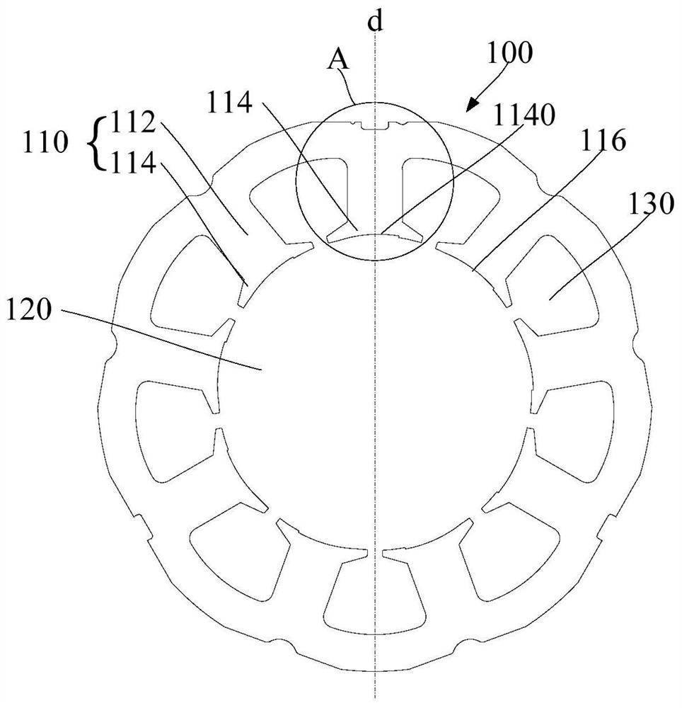
[0055] Such as figure 1 As shown, according to an embodiment of the present invention, a stator core is proposed, including: a plurality of stator punching pieces.

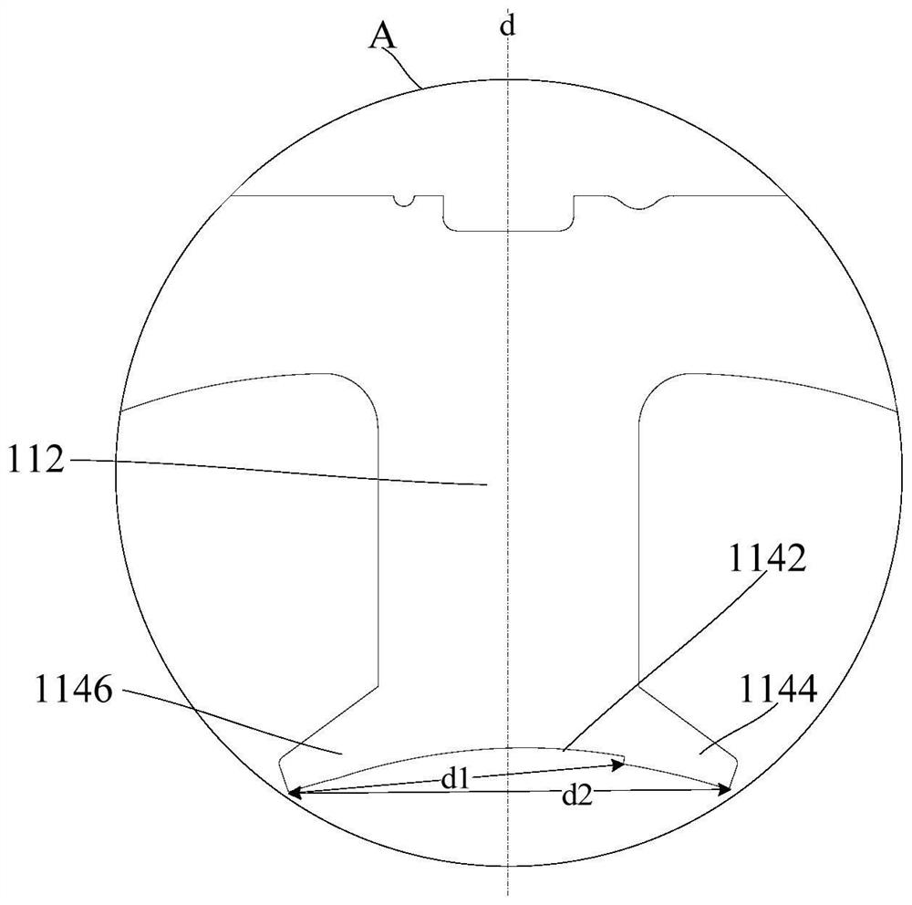
[0056] Specifically, each stator punching piece includes a plurality of stator teeth 110 distributed along the circumferential direction, and each stator tooth 110 includes: a tooth part 112 and a tooth shoe 114, and the tooth shoe 114 is arranged on the side of the tooth part 112 close to the inner hole 120 A plurality of tooth shoes 114 surround and form an inner hole 120 , and a plurality of stator stampings are stacked along the axial direction of the inner hole 120 . Wherein, the plurality of stator punching pieces include at least one first stator punching piece 100, the inner peripheral wall 116 of at least one tooth shoe 114 of the first stator punching piece 100 is provided with a recessed portion 1140, and the tooth shoe 114 includes a first tooth shoe portion 1144 , the part of the concave portion 1140...

Embodiment 2

[0063] Such as Figure 1 to Figure 3 As shown, according to an embodiment of the present invention, it includes the features defined in any of the above-mentioned embodiments, and further: on a section perpendicular to the axis of the rotor 320 , along the rotation direction of the rotor 320 , the concave portion 112 faces the side of the rotor 320 The shortest distance from any point on the inner wall surface 1142 to the rotation center of the rotor 320 gradually decreases.

[0064] In this embodiment, the rotor 320 is installed in the inner hole 120 of the stator core. On a cross section perpendicular to the axis of the rotor 320 , along the rotation direction of the rotor 320 , the concave portion 112 faces any part of the inner wall surface 1142 of the rotor 320 . The shortest distance from one point to the rotation center of the rotor 320 gradually decreases. That is, the minimum distances between two adjacent points on the inner wall surface 1142 and the rotation center...

Embodiment 3

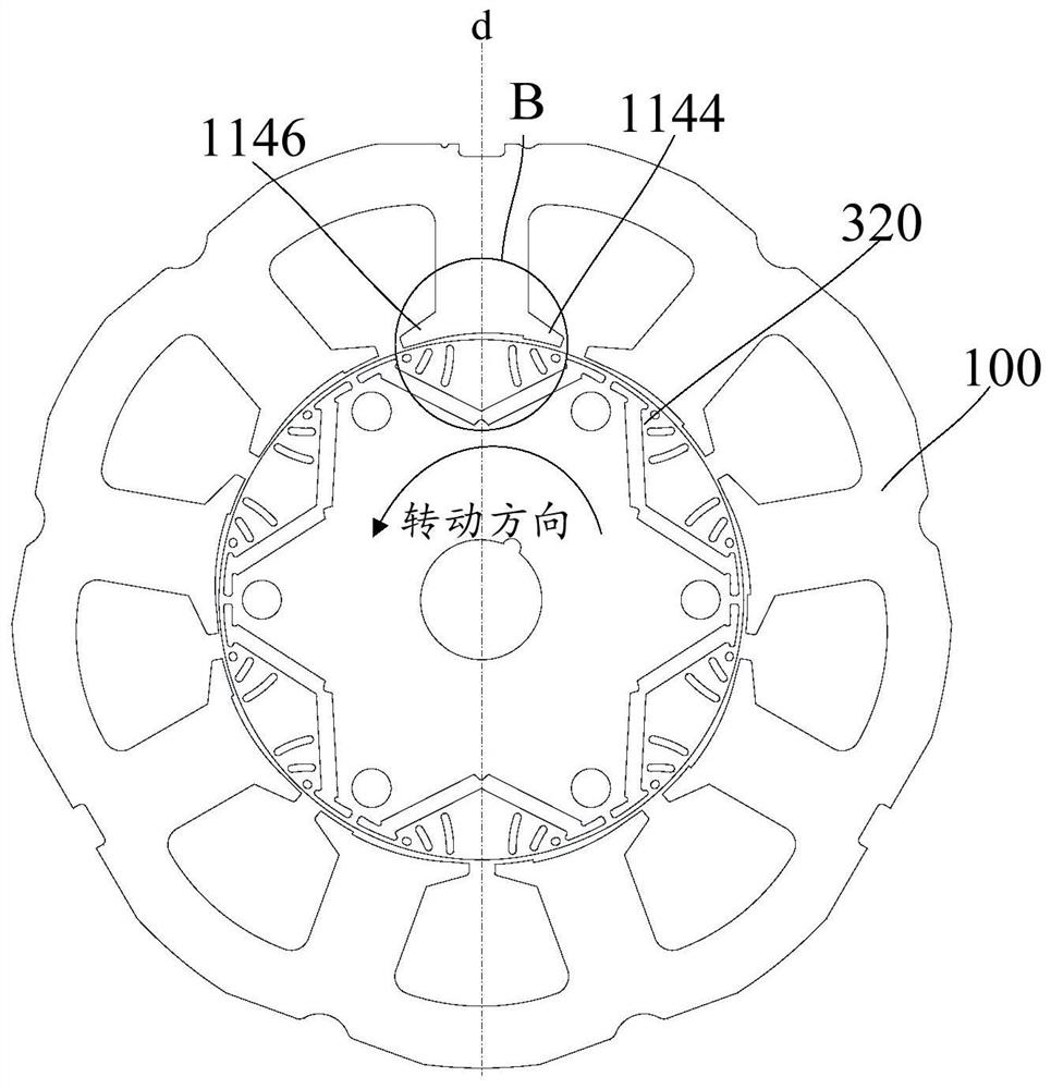
[0067] Such as Figure 1 to Figure 3 As shown, according to an embodiment of the present invention, it includes the features defined in any one of the above embodiments, and further: the tooth shoe 114 further includes: a second tooth shoe part 1146 .

[0068] In detail, along the rotation direction of the rotor 320, the second tooth shoe portion 1146 is arranged in the area where the symmetric center line d of the tooth portion 112 is away from the first tooth shoe portion 1144, and the second tooth shoe portion 1146 is provided with a concave portion 1140.

[0069] Wherein, the first tooth shoe part 1144 and the second tooth shoe part 1146 are respectively the parts of the tooth shoe 114 extending toward two adjacent stator slots.

[0070]In this embodiment, along the rotation direction of the rotor 320, a first tooth shoe portion 1144 and a second tooth shoe portion 1146 are respectively provided on both sides of the symmetric center line d of the tooth portion 112, that i...


PUM


Abstract

The invention provides a stator core, a stator, a permanent magnet synchronous motor, a compressor and refrigeration equipment. The stator core comprises a plurality of stator punching sheets, the plurality of stator punching sheets are stacked in the axial direction of an inner hole, each stator punching sheet comprises a plurality of stator teeth distributed in the circumferential direction, each stator tooth comprises a tooth part and a tooth boot connected to the tooth part, and the plurality of tooth boots form the inner hole in an enclosing mode; the plurality of stator punching sheets comprise at least one first stator punching sheet, the inner circumferential wall of at least one tooth boot of the first stator punching sheet is provided with a concave part, the tooth boot comprisesa first tooth boot part, and a part of the concave part is located in an area, facing one side of the first tooth boot part, of the symmetric center line of the tooth part. Therefore, radial electromagnetic force waves generated by the interaction of armature magnetic field harmonics and rotor magnetic field harmonics are reduced, the deformation of the stator core is reduced, the vibration noiseof a motor key frequency band is remarkably improved, and the hearing feeling of the compressor is effectively improved.

Description

technical field [0001] The invention relates to the technical field of compressors, in particular to a stator core, a stator, a permanent magnet synchronous motor, a compressor and a refrigeration device. Background technique [0002] In the related technology, in the rotary DC inverter compressor, the motor generally adopts the built-in permanent magnet motor. In the motor design with higher power density, after the motor is powered on, the time and time of the combined magnetic field generated by the stator magnetic field and the rotor magnetic field interact Spatial harmonics will generate greater vibration noise, which cannot meet the quietness and comfort required by users. Contents of the invention [0003] The present invention aims to solve at least one of the technical problems existing in the prior art or related art. [0004] To this end, the first aspect of the present invention is to propose a stator core. [0005] A second aspect of the invention consists i...

Claims


Application Information

Patent Timeline
Patent Type & Authority Applications(China)
IPC IPC(8): H02K1/12H02K1/14
CPCH02K1/12H02K1/146H02K2213/03
Inventor 徐飞邱小华江波
Owner ANHUI MEIZHI PRECISION MFG
Why Eureka
Try Eureka