Auxiliary cross beam, connecting structure of auxiliary cross beam and main beams and photovoltaic tracking support

A technology for connecting structures and beams, which is applied in the field of solar photovoltaics, can solve problems such as failure to work normally, damage of photovoltaic panels due to deformation of brackets, low torsional stiffness of photovoltaic tracking brackets, etc., to reduce the probability and magnitude of deformation, ensure structural stability, Effect of improving torsional rigidity

Pending Publication Date: 2021-03-26
SHANGHAI NENGYAO NEW ENERGY TECH CO LTD
View PDF0 Cites 1 Cited by
  • Summary
  • Abstract
  • Description
  • Claims
  • Application Information

AI Technical Summary

Problems solved by technology

[0005] The purpose of the present invention is to provide a secondary beam and its connection structure with the main beam and a photovoltaic tracking support. The photovoltaic tracking support is constructed by using double main beams, and the double main beams are connected through the main beams, and at the same time, it is combined with the connection between the main beams. The auxiliary beam is used to improve the torsional rigidity of the photovoltaic tracking bracket, and solve the problem that the photovoltaic panel cannot be installed normally due to the low torsional stiffness of the photovoltaic tracking bracket, or the photovoltaic panel cannot work normally due to deformation and damage of the bracket

Method used


Image

  • Auxiliary cross beam, connecting structure of auxiliary cross beam and main beams and photovoltaic tracking support
  • Auxiliary cross beam, connecting structure of auxiliary cross beam and main beams and photovoltaic tracking support
  • Auxiliary cross beam, connecting structure of auxiliary cross beam and main beams and photovoltaic tracking support

Examples


Embodiment 1

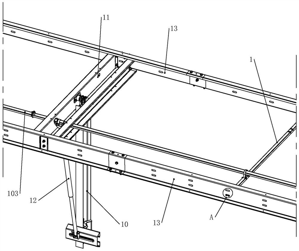
[0065] Such as figure 1 As shown, a photovoltaic tracking support includes several columns 10 , several main beams 11 , at least two main beams 13 and several transmission shafts 103 .

[0066] The columns 10 are neatly arranged on the ground, the upper end of each column 10 is hinged with the middle part of the main beam 11, the main beam 11 can rotate on the upper end of the column 10, the main beam 13 is arranged at the two ends of the main beam 11, and is connected by a bolt The connections are fixed so as to form a bracket body, and at the same time, an actuator 12 is connected to the side of each column 10, and the upper end of the actuator 12 is at two-thirds of the main beam 11, or any position except the middle position.

[0067] In order for the actuators 12 to operate synchronously, a transmission shaft 103 is provided on the main beam 11, and the two ends of the transmission shaft 103 are respectively clamped to the adjacent actuators 12, and a driving motor is pro...

Embodiment 2

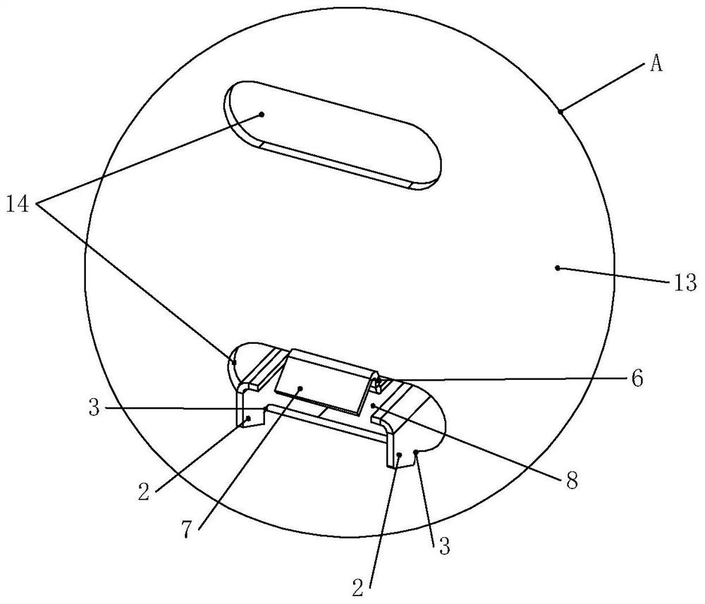
[0130] The structure is basically the same as that of Embodiment 1, the difference is: as Figure 8 As shown, the support block 114 can be made of hard plastic as a whole to ensure strength. The connecting part 102 may include a first connecting part 108 and a second connecting part 109, the first connecting part 108 is arranged on the upper end of the left fixing part 100, and the second connecting part 109 is arranged on the upper end of the right fixing part 101, while the first The upper ends of the connecting portion 108 and the second connecting portion 109 are arc-shaped.

[0131] When the left fixing part 100 and the right fixing part 101 are locked against each other, that is, the locking protrusion 105 and the third locking groove 106 are locked together to form a labyrinth gap structure, the first connecting part 108 and the second connecting part 109 It can cooperate with the left fixed part 100 and the right fixed part 101 to form a movable cavity 104 to restrain...

Embodiment 3

[0133] The structure is basically the same as other embodiments, the difference is: as Figure 19 As shown, the stopper 411 can be arranged on the upper end surface of the stop washer 409, and the shape can be a rib 427 diverging outward from the round point, and the lower end surface of the nut 410 can be arranged to match the rib 427. The groove, through the cooperation of the groove and the rib 427 , realizes the rotation limitation between the stop washer 409 and the nut 410 .


PUM


Abstract

The invention relates to the technical field of solar photovoltaics, in particular to an auxiliary cross beam, a connecting structure of the auxiliary cross beam and main beams and a photovoltaic tracking support, the auxiliary cross beam comprises an auxiliary cross beam main body, clamping grooves I are formed in the end parts of the auxiliary cross beam main body, elastic sheets are arranged onthe auxiliary cross beam main body on the back surfaces of the clamping grooves I, and abutting surfaces are formed on the outer walls of the elastic sheets; the abutting surfaces protrude towards the outer side of the auxiliary cross beam body. The outer end parts of the elastic sheets are bent to form clamping surfaces; and the clamping surfaces are used for abutting against the side surfaces of the main beams. According to the invention, the double main beams are used for constructing the photovoltaic tracking support, main cross beams are connected with the double main beams, and the auxiliary cross beams connected between the main beams are matched to improve the torsional rigidity of the photovoltaic tracking support, so that the problems that the photovoltaic panel cannot be normally installed due to low torsional rigidity of the photovoltaic tracking support or the photovoltaic panel is damaged and cannot work normally due to the deformation of the support are solved.

Description

technical field [0001] The invention relates to the field of solar photovoltaic technology, in particular to an auxiliary beam and its connection structure with a main beam, and a photovoltaic tracking bracket. Background technique [0002] Photovoltaic tracking systems are photovoltaic systems that automatically track the sun and improve overall power generation. By tracking the movement of the sun in real time, direct sunlight to the photovoltaic array, thereby increasing the amount of solar radiation received by the photovoltaic array and improving the overall power generation of the solar photovoltaic power generation system. [0003] In the photovoltaic tracking system, the solar photovoltaic bracket is the main part used to fix the photovoltaic panel and adjust the angle of the photovoltaic panel. The existing solar photovoltaic support in 2019113479939 mainly includes a column, and a main shaft is rotated at the upper end of the column, and the photovoltaic panel is ...

Claims


Application Information

Patent Timeline
Patent Type & Authority Applications(China)
IPC IPC(8): H02S20/30H02S20/32H02S40/00F24S50/20
CPCF24S50/20H02S40/00H02S20/30H02S20/32Y02E10/47Y02E10/50
Inventor 不公告发明人
Owner SHANGHAI NENGYAO NEW ENERGY TECH CO LTD
Why Eureka
Try Eureka