
Manufacturing, forming and machining system for heat exchanger fins

A technology of forming processing and heat exchangers, which is applied in the direction of manufacturing tools, metal processing equipment, heat exchange equipment, etc., can solve the problems of fins prone to burrs, cumbersome burrs, and fin surface unevenness, so as to ensure heat exchange efficiency , Realize the effect of streamlining and avoid adverse effects

Inactive Publication Date: 2021-03-30
南京华斯特机械科技有限公司
View PDF0 Cites 4 Cited by
  • Summary
  • Abstract
  • Description
  • Claims
  • Application Information

AI Technical Summary

Problems solved by technology

[0005] The invention can solve the traditional heat exchanger fin manufacturing and forming processing method. After the straight fins are manufactured, the surface of the fins is often uneven, and the existence of some irregular depressions or protrusions not only reduces heat transfer The appearance effect of the fins of the heat exchanger also affects the heat exchange rate of the fins of the heat exchanger, and the surface of the fins is prone to burrs. Because the shape of the straight fins is special, the burrs are usually removed manually. Manual deburring is cumbersome and the treatment effect is not good, which will also affect the working effect of the heat exchanger fins and other problems

Method used


Image

  • Manufacturing, forming and machining system for heat exchanger fins
  • Manufacturing, forming and machining system for heat exchanger fins
  • Manufacturing, forming and machining system for heat exchanger fins

Examples


Embodiment Construction

[0032] The embodiments of the present invention will be described in detail below with reference to the accompanying drawings, but the present invention can be implemented in many different ways defined and covered by the claims.

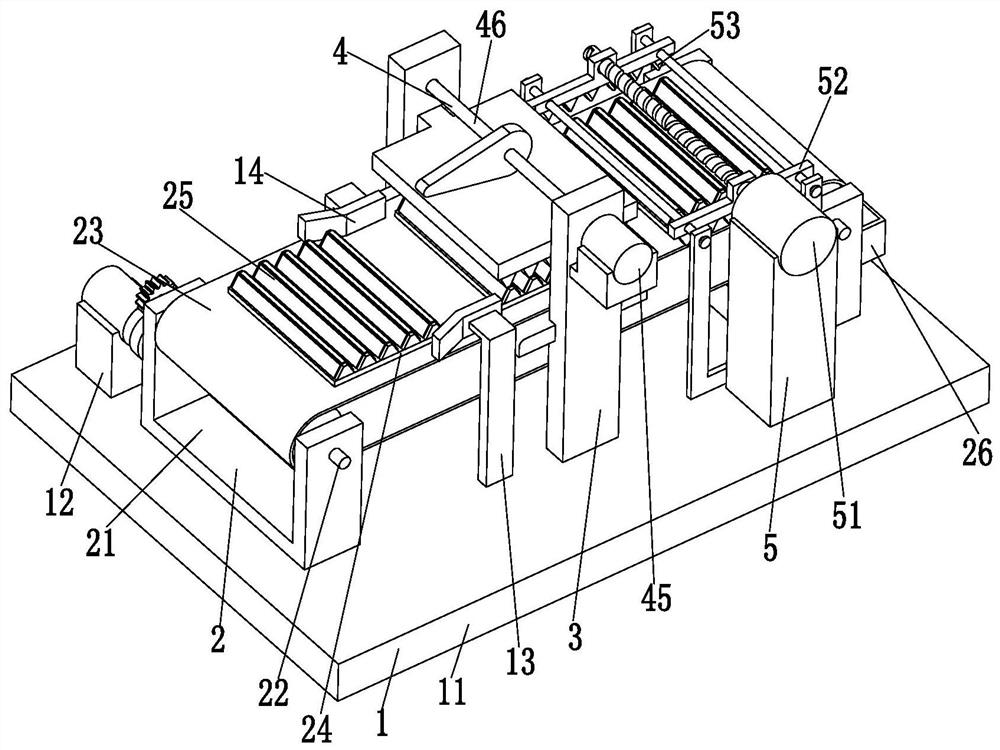
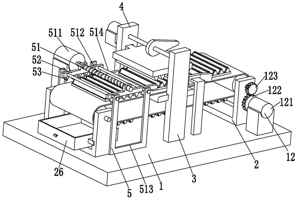
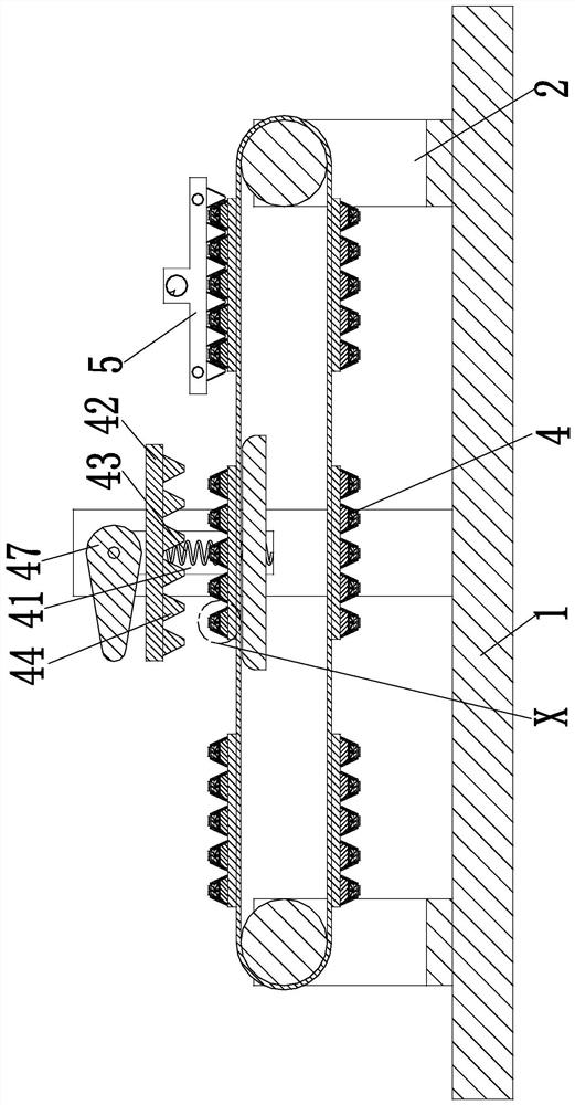
[0033] like Figure 1 to Figure 7 As shown, a heat exchanger fin manufacturing and forming processing system includes a fixed base 1, a U-shaped frame 2, a rectangular plate 3, a correction mechanism 4 and a cleaning mechanism 5, and the left and right sides of the upper end of the fixed base 1 are installed symmetrically. There is a U-shaped frame 2, a rectangular plate 3 is symmetrically fixed on the front and rear sides of the upper middle part of the fixed base 1, a rectifying mechanism 4 is arranged on the rectangular plate 3, and a cleaning mechanism 5 is arranged on the right side of the upper end of the fixed base 1; the rectangular plate The middle part between 3 is connected with the working plate, and the working plate is close to the inn...


PUM


Abstract

The invention relates to a manufacturing, forming and machining system for heat exchanger fins. The manufacturing, forming and machining system comprises a fixing base, U-shaped frames, rectangular plates, correcting mechanisms and a cleaning mechanism; the U-shaped frames are symmetrically installed on the left side and the right side of the upper end of the fixing base; the rectangular plates are symmetrically fixed to the front side and the rear side of the middle of the upper end of the fixing base; the correcting mechanisms are arranged on the rectangular plates correspondingly; and the cleaning mechanism is arranged on the right side of the upper end of the fixing base. The manufacturing, forming and machining system provided by the invention can solve the problems that according toa traditional manufacturing, forming and machining method for heat exchanger fins, after fin manufacturing is completed, the surface of each fin is usually uneven, due to the existence of some irregular recesses or protrusions, the appearance effect of the heat exchanger fins is reduced; meanwhile, the heat exchange rate of the heat exchanger fins is affected as well, burrs are prone to appearingon the surfaces of the fins; moreover, the shape of a straight fin is special, so burrs are tedious to be removed manually, the treatment effect is poor, and the working effect of the heat exchanger fins is affected as well, and the like.

Description

technical field [0001] The invention relates to the technical field of heat exchanger manufacturing and molding, in particular to a heat exchanger fin manufacturing and molding processing system. Background technique [0002] A heat exchanger is a device that transfers part of the heat of a hot fluid to a cold fluid, also known as a heat exchanger. As an energy-saving device that realizes heat transfer between materials between two or more fluids at different temperatures, the heat exchanger can transfer heat from a fluid with a higher temperature to a fluid with a lower temperature, so that the temperature of the fluid reaches the process level. The specified index is to meet the needs of the process conditions, and the heat exchanger is also one of the main equipment to improve energy utilization. The finned radiator is the most widely used heat exchange equipment in heat exchangers. It achieves the purpose of enhancing heat transfer by adding fins to ordinary base tubes....

Claims


Application Information

Patent Timeline
Patent Type & Authority Applications(China)
IPC IPC(8): B21D1/00B21D19/00B21D21/00B21D43/12B21D53/02
CPCB21D1/00B21D19/005B21D21/00B21D43/12B21D53/022
Inventor 不公告发明人
Owner 南京华斯特机械科技有限公司
Learn More